77
Troubleshooting
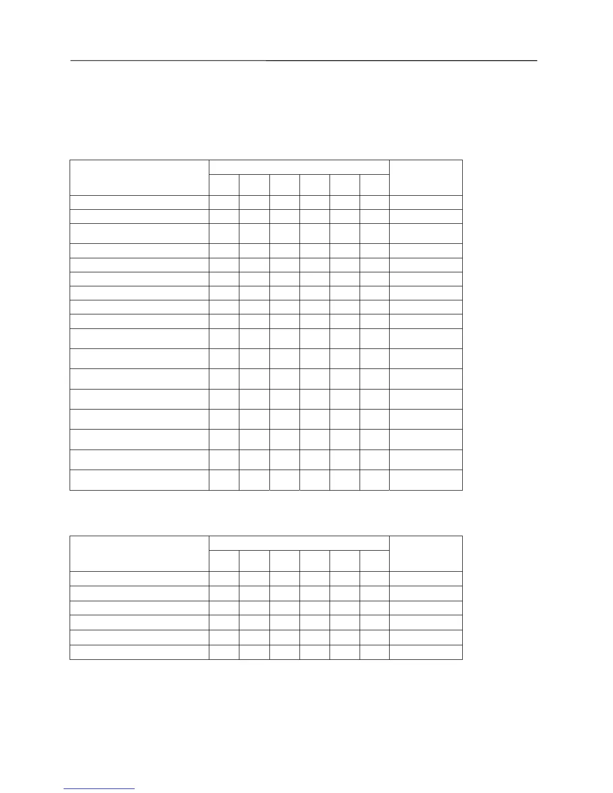
Trouble and State Display of Mainboard LED of Outdoor Unit。
Definition:
z LED6: Power lamp (red), bright when energized.
z LED5: Operation lamp (green), bright if no error, which indicates that the unit is started; “Dark”
indicates the unit is stopped.
z LED4、LED3、LED2、LED1: Error / state indicator (yellow)
1. Trouble of elements
Display of LED
Trouble name
LED6 LED5 LED4 LED3 LED2 LED1
Display of
wired remote
controller
High-pressure sensor error
○ ○
Fc
Low-pressure sensor error
○ ○ ○
Fd
Outdoor environment temperature
sensor error
○ ● ● ●
F4
System 1 coil-inlet sensor error
○ ● ●
F5
System 1 coil-inlet sensor error
○ ● ●
F6
System 1 coil-inlet sensor error
○ ●
F7
System 2 coil inlet temp. sensor fault
○ ● ○ ●
F5
System 2 coil-middle sensor error
○ ● ○
F6
System 2 coil-exit sensor error
○ ● ● ○
F7
Inverter/Digital exhaust temperature
sensor error
○ ●
F9
Fixed-frequency compressor 1
exhaust temperature sensor error
○ ● ●
F8
Fixed-frequency compressor 2
exhaust temperature sensor error
○ ● ○
F8
Fixed-frequency compressor
3exhaust temperature sensor error
○ ● ○ ○
F8
Inverter/Digital oil temperature / top
sensor error
○
Fb
Fixed-frequency compressor 1 oil
temperature / top sensor error
○ ●
FA
Fixed-frequency compressor 2 oil
temperature / top sensor error
○ ● ○
FA
Fixed-frequency compressor 3 oil
temperature / top sensor error
○ ○ ●
FA
Legend: bright ○; dark ●;blink
2.System trouble
Display of LED
Trouble name
LED6 LED5 LED4 LED3 LED2 LED1
Display of
wired remote
controller
High-pressure protection
○ ● ● ●
E1
Low-pressure protection
○ ● ● ●
E3
Exhaust protection
○ ● ●
E4
Overcurrent Protection
○ ● ● ●
E5
Oil temperature 85 protection℃
○ ○
E4
No-refrigerant protection
○ ○ ●
E3
Legend: bright ○; dark ●;blink
 Loading...