GMV5 D.C INVERTER MULTI VRF SERVICE MANUAL
198
3 KEY PARTS MAINTENANCE
3.1 CAUTIONS ON CONTROLLER AP1 REPLACEMENT
3.1.1 Cautions on ODU AP1 Replacement
3.1.1.1 Distinguishing Master Module from Slave Module
Before replacing ODU AP1, determine the module is a master ODU or a slave ODU. They can be
distinguished based on:
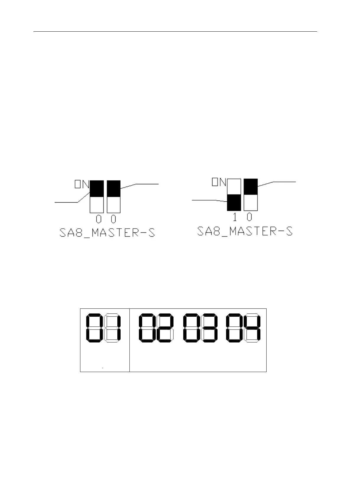
(1) ―Master module DIP state (SA8_MASTER-S)‖
Every cooling system has only one master module (set in power-off state). When a DIP is ―ON‖, the
corresponding position is ―0‖; when the DIP is ―OFF‖, the corresponding position is ―1‖. If
SA8_MASTER-S is set to ―00‖, it indicates a master module; if it is set to ―10‖, it indicates a slave module
(as shown in the figure below).
DIP setting
position
DIP setting
position
DIP setting
position
DIP setting
position
Master module state
Slave module state
(2) AP1 LED
When a master module is powered on, LED1 is displayed as ―01‖. For a slave module, LED1 is
displayed as ―02‖, ―03‖ or ―04‖ (as shown in the figure below).
LED1 display state
Master module state
LED1 display state
Slave module state
LED1 display state
Slave module state
LED1 display state
Slave module state
Or
Or
3.1.1.2 Cautions on Replacement of Master ODU AP1
Before replacing master module AP1, make the following preparations:
(1) Master module DIP setting
Set the new AP1 identical to the faulty AP1. Note that settings must be performed when the master
ODU is powered off and they will take effect after the ODU is powered on. Settings that are performed in
power-on state are invalid.
(2) Communication state check

 Loading...

