GMV5 D.C INVERTER MULTI VRF SERVICE MANUAL
203
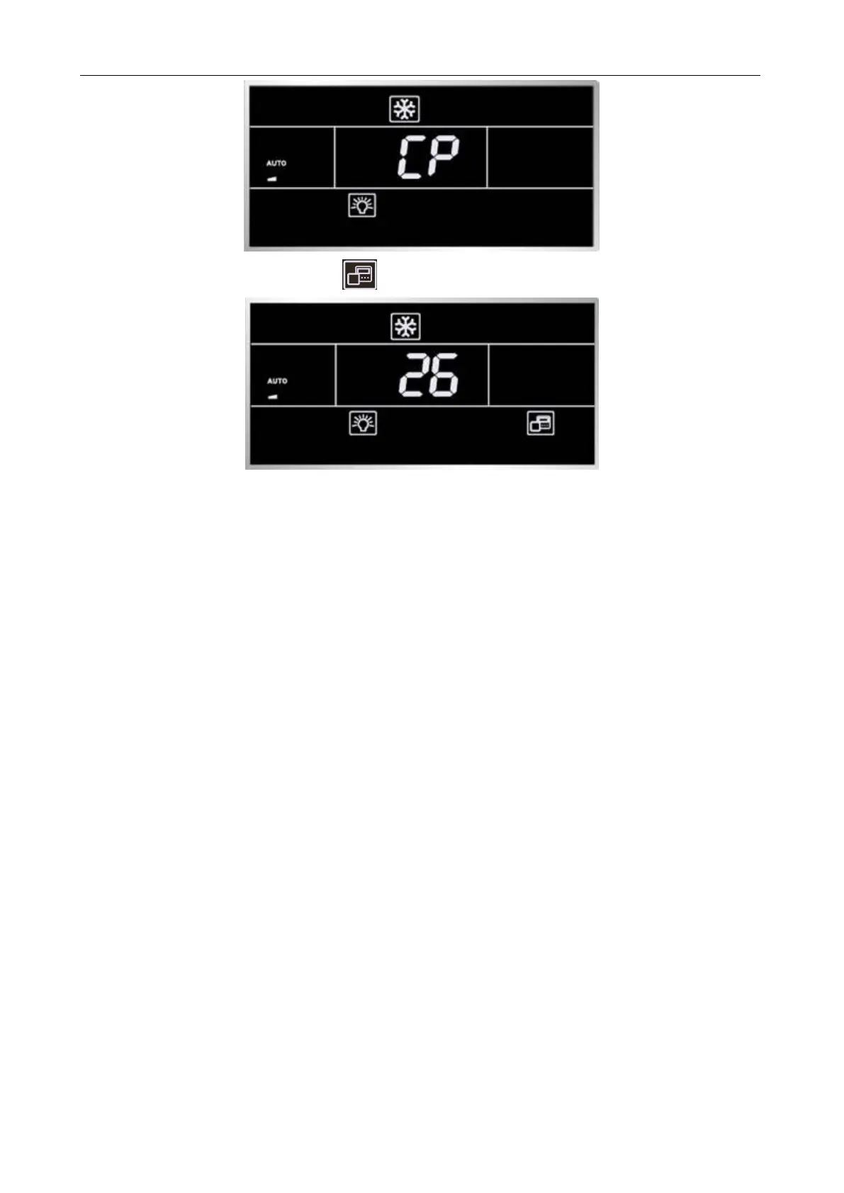
After setting, the LCD displays the icon, as shown in the figure below.
NOTE:
All wired controls are set to master wired controls by default.
(4) If the AP1 of the master IDU is replaced,
Reset the master IDU through the wired control; otherwise, the LCD displays L7 (no master IDU).
There are two methods to set the IDU:
1) In shut mode, press and hold the ―MODE‖ button for 5 seconds and set the IDU corresponding to
this wired control to a master IDU. After setting, the ―Main‖ icon is highlighted.
2) Set the wired control parameter ―P10‖ to 1.
3.1.3.2. Cautions on Wired Control XK49 Replacement
To replace the wired control XK49, in addition to the preceding handling steps specific for XK46, you
should also configure access control.
(1) If the wired control does not need an access control system, set switch ―1‖ for DIP S1 at the
bottom of the wired control to digital end (neglect switch ―2‖).
(2) If the wired control needs an access control system, set switch ―1‖ for DIP S1 at the bottom of the
wired control to ON (neglect switch ―2‖) and connect the access control card interface to ports N and L or
ports VCC and GND of the wiring terminal. The following should be noted:
1) Ports N and L are power interfaces of 100-240V~50/60Hz access control.
2) Ports VCC and GND are power interfaces of DC 5-24V access control.
3) Either of them can be selected at one time.

 Loading...

