Intelligent Controller
4
5.1.3 Communication Interface
CAN comm port: connect it to the AC unit through the 2-core communication
line to realize the communication between Controller and the AC which adopts CAN
protocol.
RS485-1 comm port:this device will not use this interface temporarily.
RS485-2 comm port: this device will not use this interface temporarily.
USB and SD card port: this device will not use this interface temporarily.
Ethernet comm port ETH0:communicate with Intelligent Remote Eudemon
system via netting twine.
Ethernet comm port CONFIG: this device will not use this interface temporarily.
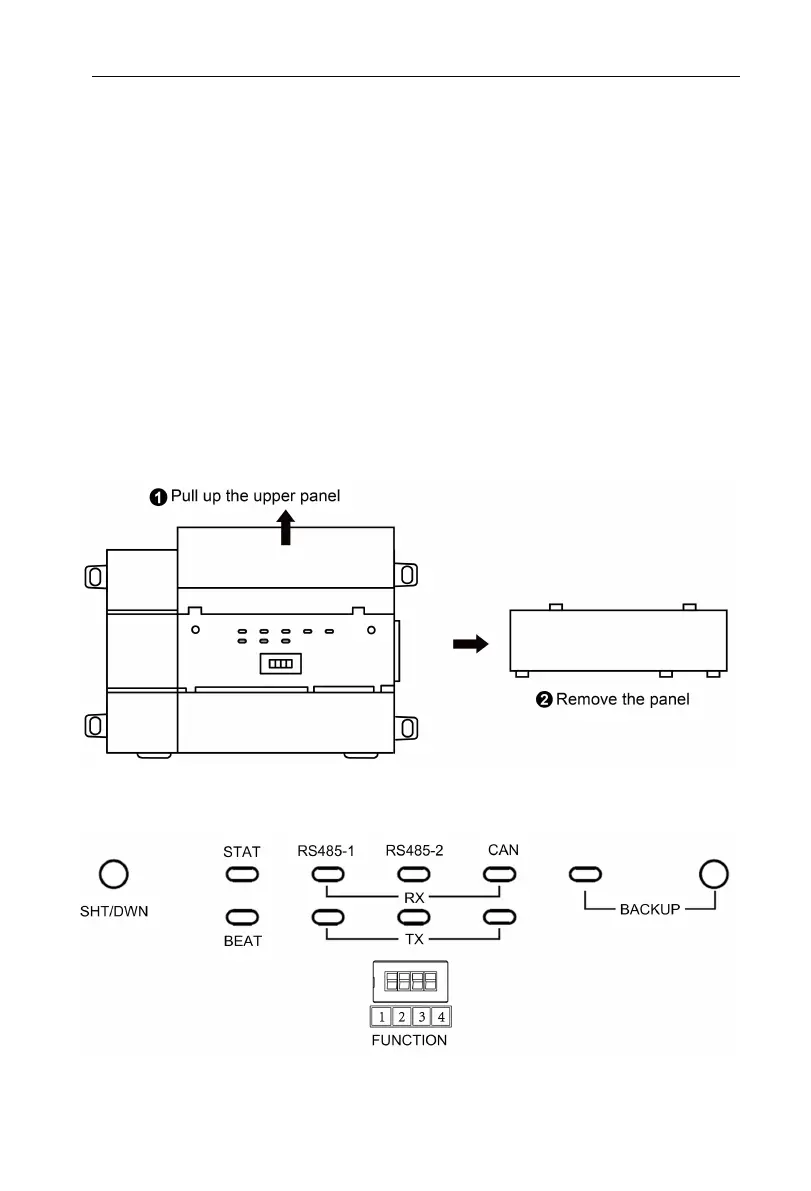
5.2 LED Display
As shown in the picture below, open the black transparent front panel.
Fig 5.2 Schematic diagram of opening the black transparent board
Indicators, buttons and DIP switch are as shown below.
Fig 5.3 The schematic diagram of the Controller LED light board and DIP switch
The above LED indicator is mainly consist of two parts: status indicator (run,
 Loading...