Intelligent Controller
24
Step 1: Connect the RS485-1 communication interface A+ and B- port of the
smart controller to the A and B port of KWH meter; Step 2: Conduct serial
connection with communication cord 485 for the KWH meter in a Intelligent Remote
Eudemon System, as is shown in Fig 8.3.
NOTE!
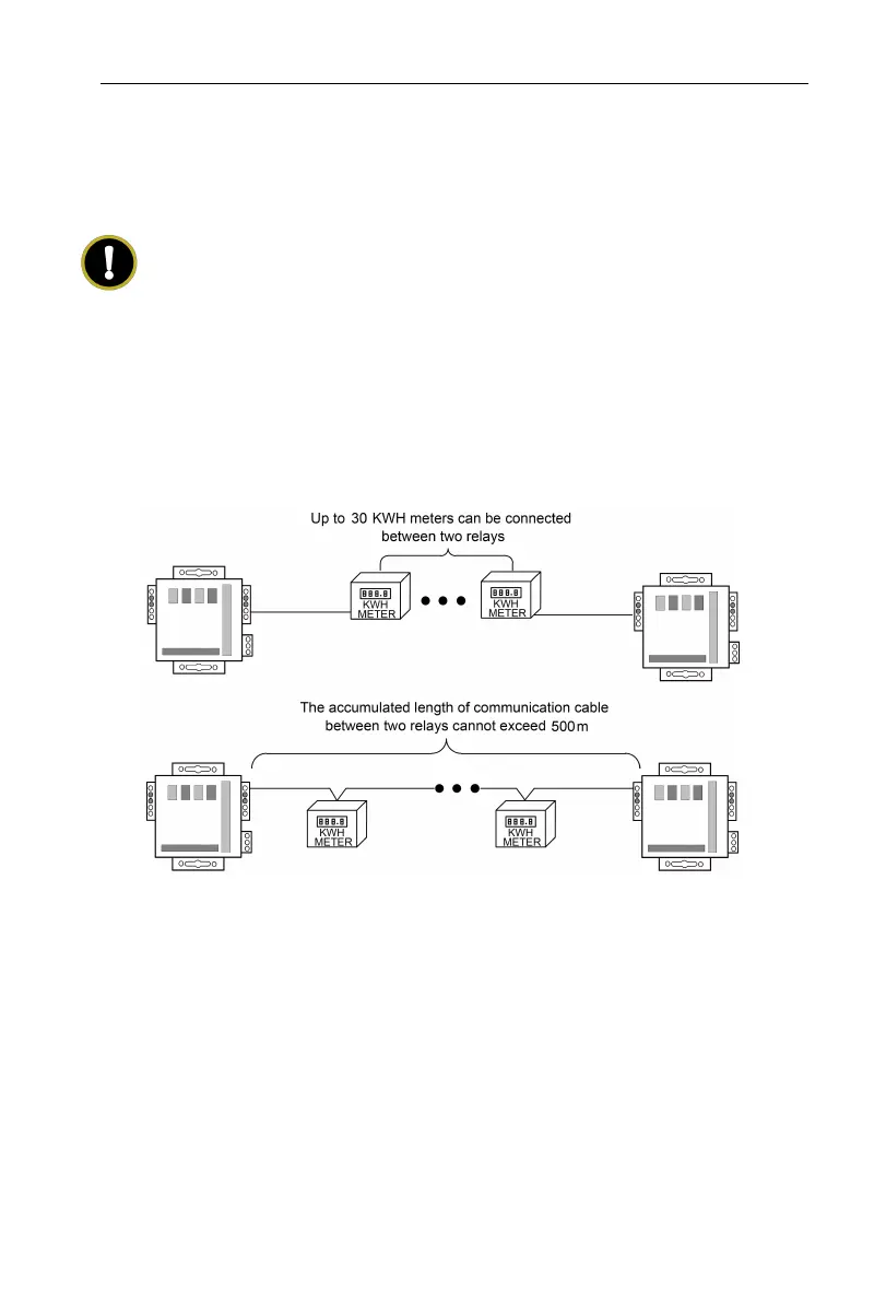
In an RS485 bus, when there are more than 30 KWH meters connected or the
communication distance is over 500m, an optoelectronic isolated relay device
must be connected. Connect the R+, R- terminals of the relay device to the A, B
terminals of RS485 communication port of a nearby KWH meter (i.e. R+ terminal
of relay connects to A terminal of KWH meter. R- terminal of relay connects to B
terminal of KWH meter).
Fig 8.4 Optoelectronic isolation repeater connection among KWH meters
8.5 Function debugging
8.5.1 Function debugging of controller
The intelligent controller is an important component of the Intelligent Remote
Eudemon System, which must ensure the normal and reliable operation of the
intelligent controller;
(1) Before the intelligent controller is energized, the CAN2 bus of the unit must
be connected to the CAN interface of the intelligent controller;
 Loading...