15
DC Inverter Multi VRF System II
Service Manual
CONTROL
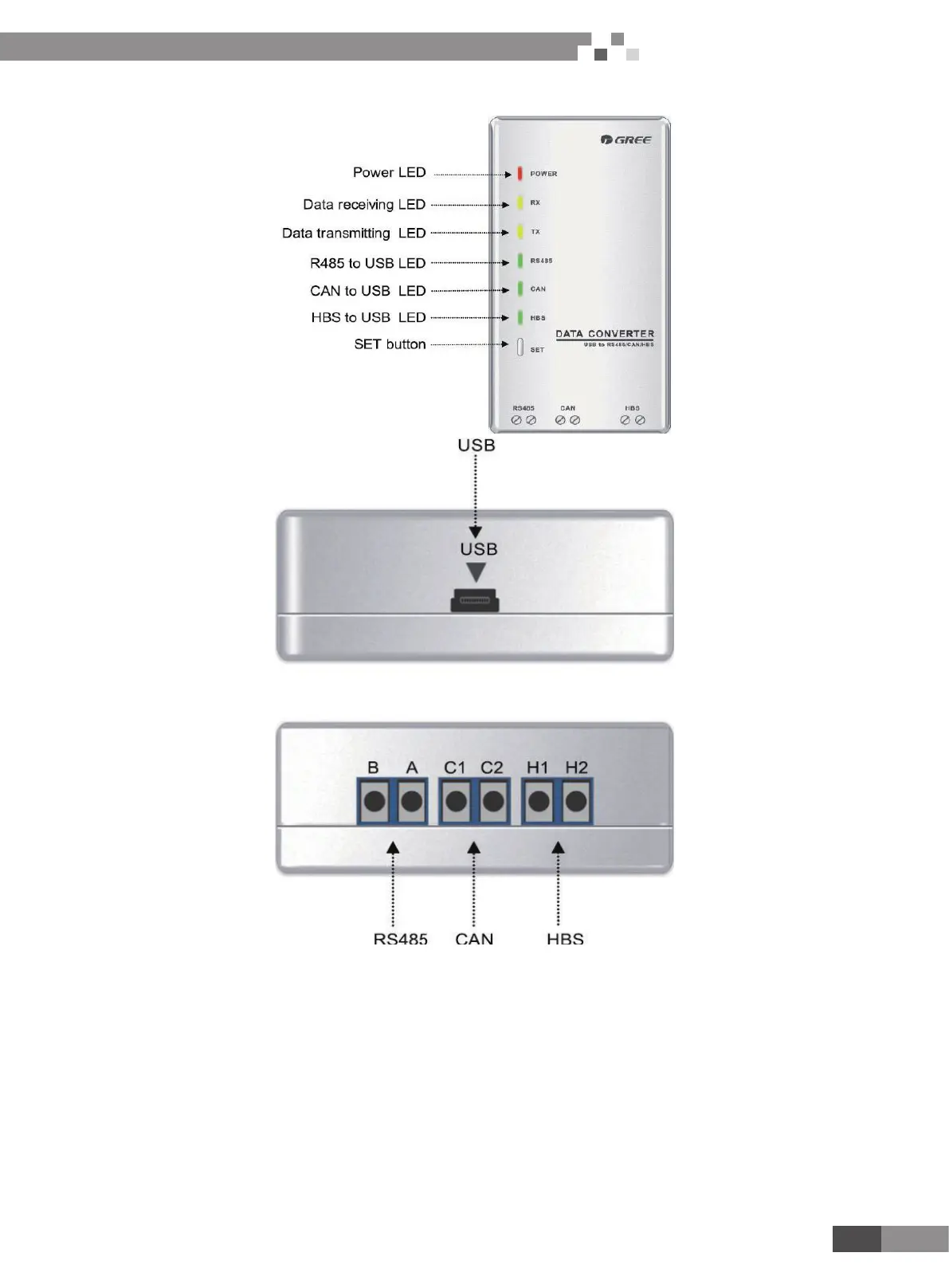
4.3.2.2 Appearance
4.3.2.3 Operation instruction
ّ
Power LED: a red light. If the red light is on, it indicates normal power supply. If the red light is off, it indicates the power supply of
converter is not normal.
ّ
Communication LEDs: yellow lights. When converter is working and the computer is transmitting data, the TX data transmitting light
will be ickering. When units are uploading data to the computer, the RX data receiving light will be ickering.
ّ
When converter is under RS485 data transferring mode, the function LED of RS485 to USB will be on.
When converter is under CAN data transferring mode, the function LED of CAN to USB will be on.
When converter is under HBS data transferring mode, the function LED of HBS to USB will be on.
ّ
USB interface: connect USB data wire.
ّ
CAN interface: When converter is under CAN communication mode, connect air conditioner’s CAN data interface. CAN interface
exhibits no polarity (A and B are equal).
ّ
HBS interface: When HBS converter is under HBS communication mode, connect air conditioner’s HBS data interface. HBS
interface exhibits no polarity (This interface is not yet available for Gree debugger and the monitoring software).

 Loading...


