68
DC Inverter Multi VRF System II
Service Manual
(17) AC current protection for inverter compressor
(18) Communication malfunction between main contoller and driver of inverter compressor
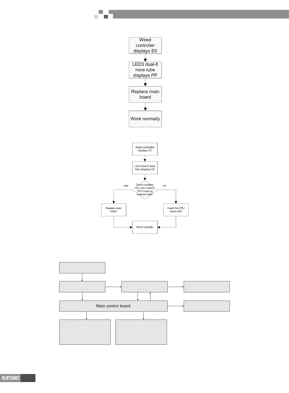
4 Power Distribution of Unit
4.1 Power distribution of unit
The control logical relationship among parts inside the electric box of unit is showed by the mongline diagram (CAD source le).
The main loop is showed by bold line (line width: 1mm); the control loop is showed by slim line (line width: 0.2mm).
Filter plate Drive board
Compressor
Fan
Power wiring board
4-way valve,by-pass
valve,electric heating belt
and control signal
Temperatuer sensor,electric
expansion valve,high
pressure and low pressure
switch and so on
(
Bold line is the power line and the slim line is the control line
)

 Loading...


