5
DC Inverter Multi VRF System II
Service Manual
PRODUCT
6 PRINCIPAL OF OPERATION
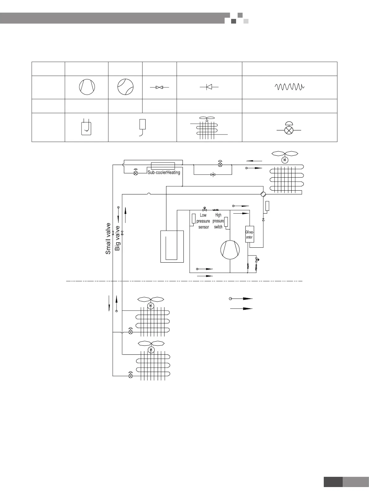
Components in owcharts are presented according to the following table:
Name Compressor 4-way valve Cut-off valve One-way valve Capillary tube
Symbol
Name
Gas-liquid
separator
Pressure
switch
Pressure
sensor
Axial-ow nned heat
exchanger
Electronic expansion valve
Symbol
Outdoor side
Indoor side
Heating
Solenoid valve
Cooling
Solenoid valve
High pressure
sensor
Pressure regulator valve
In cooling, the low-temperature and low-pressure refrigerant gas from each indoor heat exchanger will be merged and inhaled by the
compressor and then become high-temperature and high-pressure gas, which will later be discharged into outdoor heat exchangers. By
exchanging heat with outdoor air, refrigerant will turn to liquid and ow to each indoor unit via Y-type branch or manifold. Pressure and
temperature of the refrigerant will then be lowered by throttle elements before it ows into indoor heat exchangers. After exchanging heat
with indoor air, refrigerant wil become low-temperature and low-pressure gas again and repeat the circulation so as to realize the cooling
effect. In heating, 4-way valve will be energized to make refrigerant circulate in a reverse direction of cooling. Refrigerant will release heat in
indoor heat exchangers (electric heating elements will also work under certain circumstance and release heat) and absorb heat in outdoor
heat exchangers circularly so as to realize the heating effect.

 Loading...


