7
DC Inverter Multi VRF System II
Service Manual
CONTROL
CONTROL
1 Units’ Control
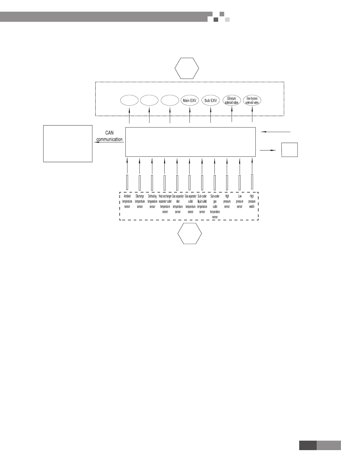
(1) Schematic diagram of units’ control
Wired controller,
remote controller
or remote monitor
Fan
Compressor
4-way valve
Control
input
Control
output
Power supply
Digital
display tube
ODU control main board
88
(2) Interpretation on the schematic diagram
ّ
High pressure switch is used to identify system’s high and low pressure. When pressure is too high, the switch will break off and
send a signal to main board. Main board will pass this signal to controller, where the error will be displayed, and stop unit from
working.
ّ
High/low pressure sensor is used to test unit’s high/low pressure and send real-time data to controller, which will control each unit’s
output according to the control logic.
ّ
Temperature sensors are used to test the tube temperature of the unit and send data to the controller, which will control each unit’s
output according to the control logic.
2 Wired Controller
2.1 Control panel

 Loading...


