8
DC Inverter Multi VRF System II
Service Manual
CONTROL
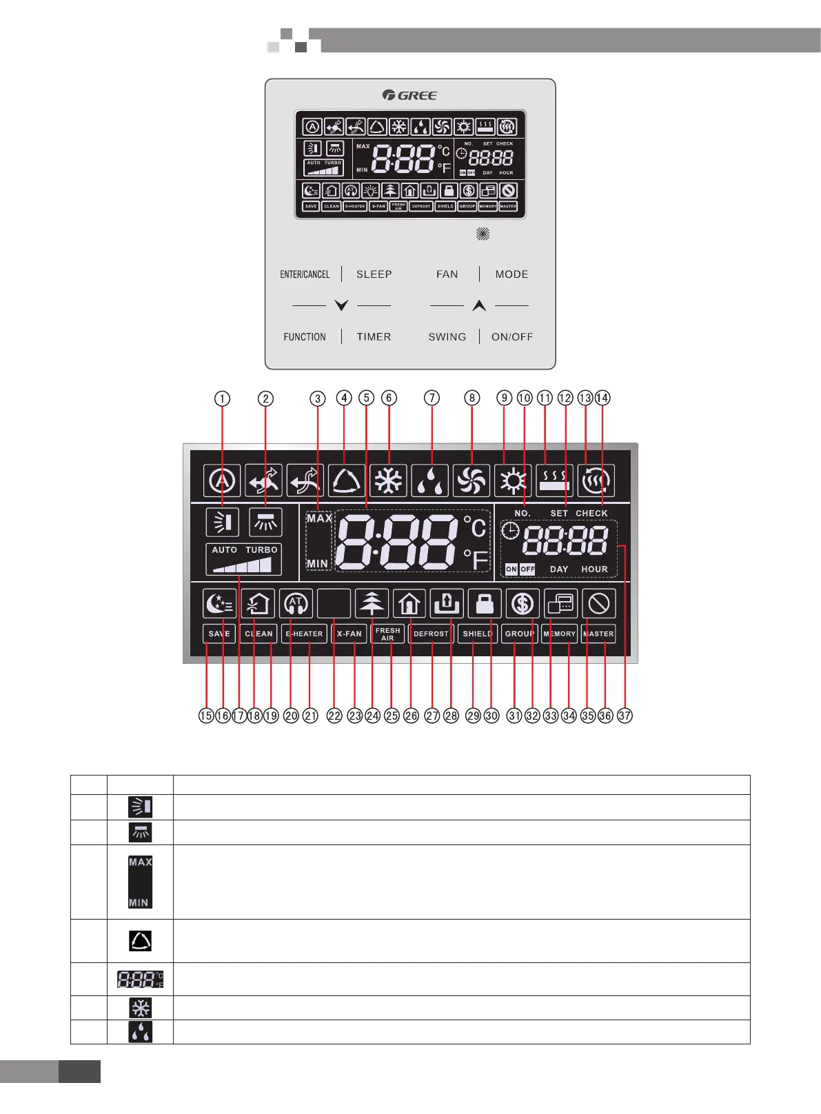
Fig. 1.1 Appearance of wired controller
Fig. 1.2 LCD graphics of wired controller
ّ
LCD Display Instruction
Table 1.1 LCD display instruction
No. Symbols Instructions
1 Up and down swing function
2 Left and right swing function
3
It's valid under Save mode and displays during setting process.
Temperature lower limit for Cooling: Limit the minimum temperature value under Cooling or Dry mode.
Temperature upper limit for Heating: Limit the maximum temperature value under Heating, Space Heating or 3D
Heating mode.
4
Auto mode (Under Auto mode, the indoor units will automatically select their operating mode as per the temperature
change so as to make the ambient comfortable.)
5
It shows the setting temperature value(In case the wired controller is controlling a Fresh Air Indoor Unit, then the
temperature zone will display FAP)
6 Cooling mode
7 Dry mode
 Loading...


