9
DC Inverter Multi VRF System II
Service Manual
CONTROL
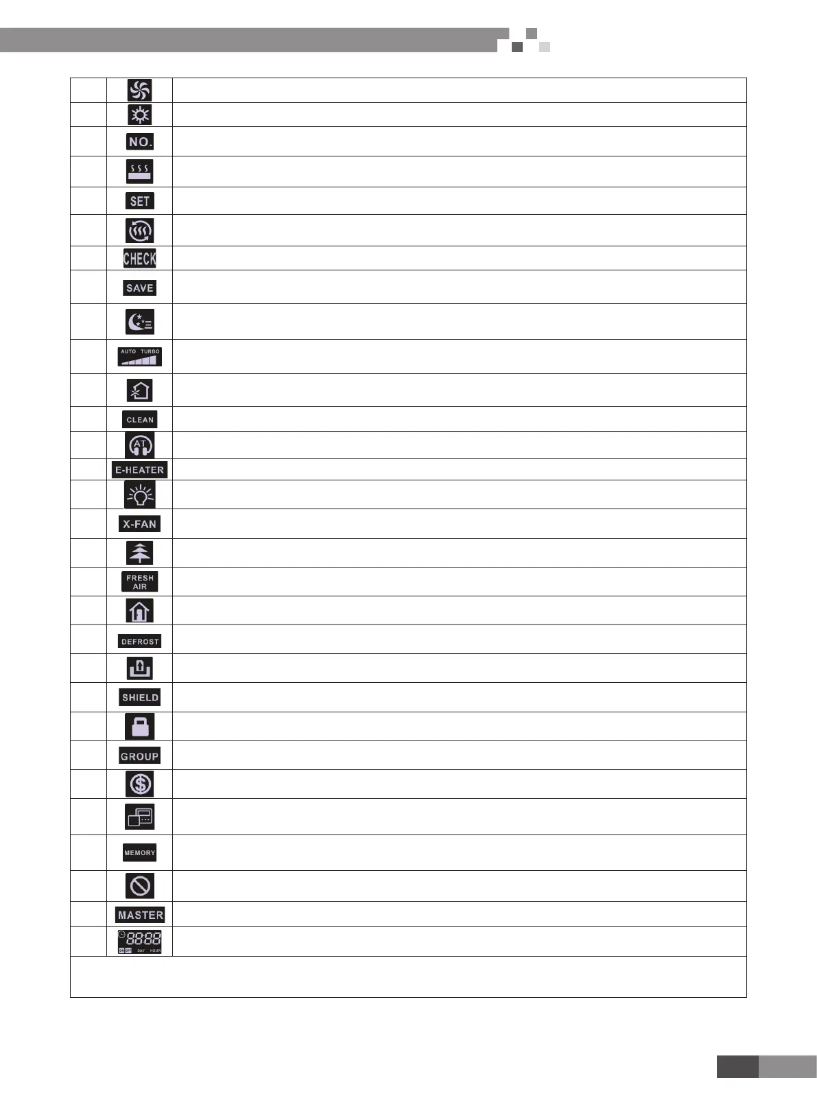
8 Fan mode
9 Heating mode
10 When inquiring or setting project number of indoor unit, it displays "NO." icon
11
Floor Heating mode (When Heating and Floor Heating simultaneously shows up, it indicates 3D Heating is
activated.)
12 Display "SET" icon under parameter setting interface
13 Space Heating mode
14 Display "CHECK" icon under parameter view interface
15 Outdoor unit operates under Save mode/upper limit of system capacitor less 100%/remote Save status
16 Sleep status
17
Current set fan speed (including auto, low speed, medium-low speed, medium speed, medium-high speed, high
speed and turbo seven status)
18 Air status
19 Remind to clean the lter
20 Quiet status (including Quiet and Auto Quiet two status)
21 Allow auxiliary electric heating On icon
22 Light On/Off function
23 X-fan function
24 Health function
25 Fresh air status
26 Out function
27 Outdoor unit defrosting status
28 Gate-control function
29 Shielding status
30 Child Lock status
31 One wired controller controls multiple indoor units
32 Save status of indoor unit
33 It indicates the current wired controller is the slave wired controller (address of wired controller is 02)
34 Memory status (The indoor unit resumes the original setting state after power failure and then power recovery)
35 Invalid operation
36 Current wired controller connects master indoor unit
37 Timer zone:Display system clock and timer status
Note: When wired controller is connected with different indoor units, some functions will be different

 Loading...


