10
DC Inverter Multi VRF System II
Service Manual
CONTROL
ّ
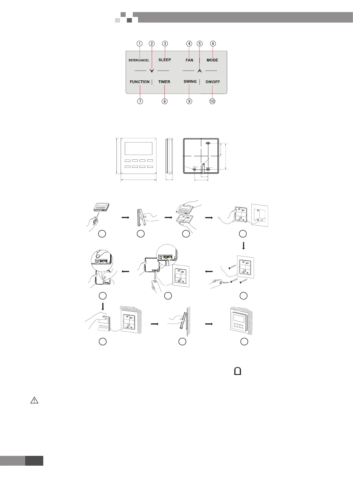
Button Graphics
Fig. 1.3 Button graphics
2.2 Installation and removal
2.2.1 Installation dimensions
Unit:mm
112
22
5
3
82.5
40
112
42.5
R3.3
6
-R
2
.7
22
Unit:mm
Fig.2.1.1 Dimension of wired controller
2.2.2 Installation method
10
1 2 3 4
67
8 9
H1H2
H1H2
H1H2
5
Fig. 2.2.2 Installation diagram for wired controller
Above is a simple installation method of wired controller. Please pay attention to the following:
1) Before installation, disconnect power of the indoor unit. Do not operate when power is connected.
2) 2-core twisted pair cable from the installation hole on the wall and lead it through the hole on the back plate of wired controller.
3) Place the wired controller on wall and secure its back plate on wall with screw M4X25.
4) Connect the 2-core twisted pair cable to terminal H1 and terminal H2. Tighten up the screws.
5) Stick the cable in the slot that is left of the terminals and buckle the wired controller’s panel with its back plate.
Note:
If caliber of the communication cord is too large, which causes difculty in leading or sticking the cord according to above point 2 and
point 5, strip some of the sheath of the communication cable to meet the installation requirement.

 Loading...


