51
DC Inverter Multi VRF System II
Service Manual
DEBUGGING & MAINTENANCE
1 Debugging of Unit
Caution:
① .
After the initial installation is nished and the main board of outdoor unit is replaced, it must perform debugging. Otherwise, the unit
can’t operate.
② .
The debugging must be performed by professional person or under the the guide of professional person.
1.1 Preparation for debugging
(1) Do not disconnect the power before the installation is nished,
(2) All wires for controller and electric wires must be connected correctly and reliably.
(3) Check the the xing ring of the foot of compressor for transportaion is removed.
(4) Remove all sundries from the unit, such as metal chips, joint, forceps holder, and so on.
(5) Check whether the appearance and pipeline system are damaged during carry or transportation process.
(6) Calculate the required added refrigerant-charging volume according to the length of pipe of system and pre-charge the refrigerant.
If refrigerant can’t be added any more when the required refrigerant-charging volume hasn’t been reached, record to refrigerant
volume which still needs to be added and continue to add refrigerant during run test operation process. Please refer to below run
test for the refrigerant-adding stage during run test process.
(7) After adding refrigerant, please make sure the valve for outdoor is opened completely.
(8) For the convenient of troubleshooting, the unit can’t be connected to the PC which installed with related debugging software and
make sure that the the datas in real time of this unit can be inspected by this computer. Please refer to Service Manual for the
installation and connection of the bebugging software.
(9) Before turn test, please do make sure that the preheat time for compressor is 8h above and touch the compressor to see whether
preheat is normal. You can perform run test only after normal preheat. Otherwise, it may damage the compressor.
1.2 Debugging of unit
Debugging procedure for test run, display instruction for indicator on main board of outdoor unit and operation method are as below:
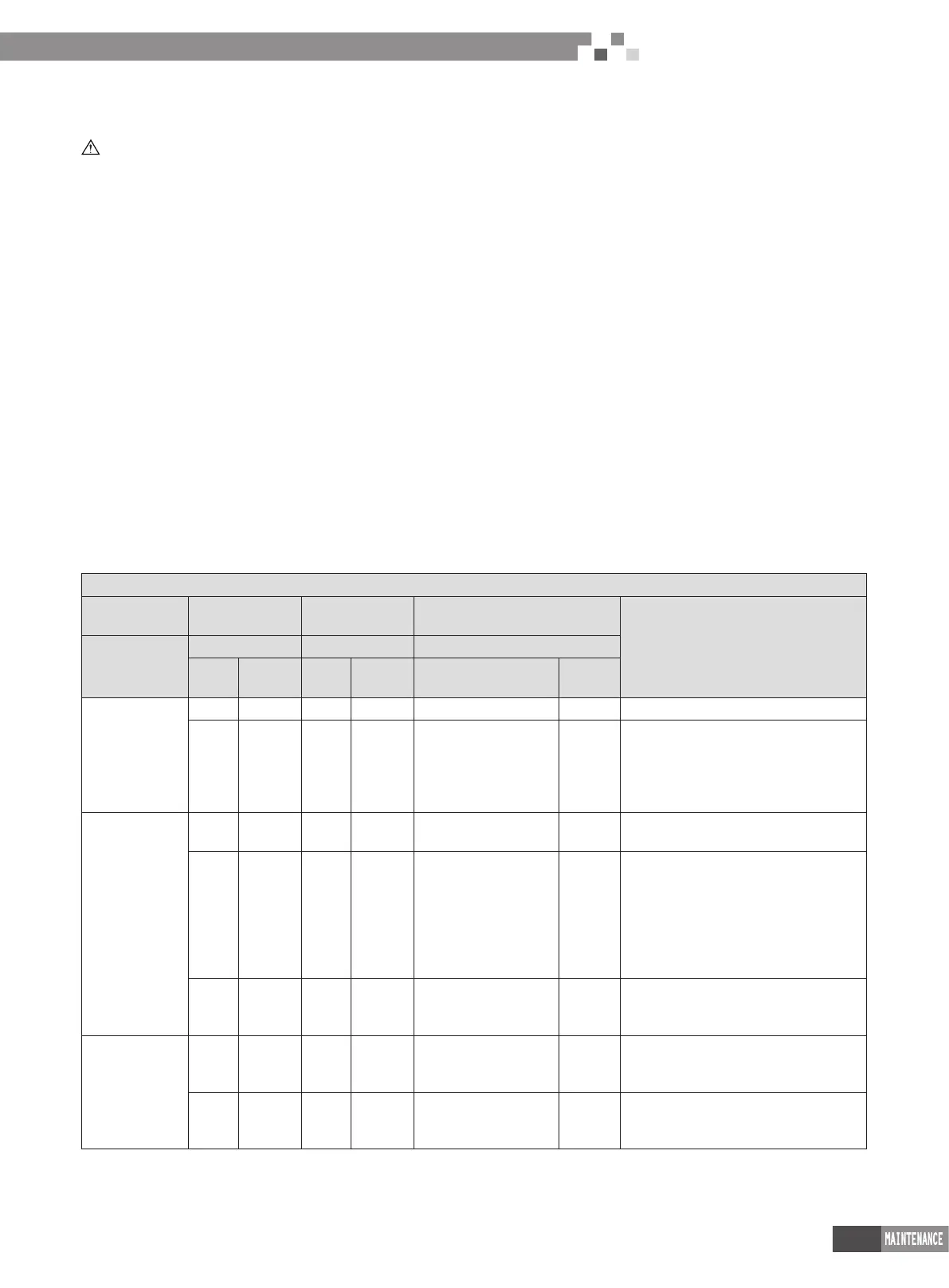
Stage process instruction for debugging
—— Debugging code
Process code
Status code
Code instruction and operation method
Process
LED1 LED2 LED3
Code
Display
status
Code
Display
status
Code
Display
status
01_ Main
control unit
setting
db ON 01 ON AO ON No debugging status for system
db ON 01 ON OC ON
Press SW7 button on main board for 5s
to start system debugging. The indicator
on main board is displayed as shown
in the left. 2s later, it will enter into next
step determination.
02_ Address
distribution
db ON 02 ON Ad Flash
Address distribution for the system. 10s
later, the display is as below:
db ON 02 ON L7 Flash
No main indoor unit. Display will be
kept for 1min. Within 1min, set the
main indoor unit through debugging
software. If notset the main indoor
unit by hand within 1min, the system
will automatically set the minimum IP
address as the main indoor unit.
db ON 02 ON OC ON
The distribution for the system address
is nished. 2s later, it will enter into the
next step determination automatically.
03_Quantity
conrmation of
outdoor unit
db ON 03 ON 01 Flash
Cormation process of system. 1s
later, it will enter into the next step
automatically.
db ON 03 ON OC ON
Cormation process of system. 2s
later, it will enter into the next step
automatically.

 Loading...


