44
DC Inverter Multi VRF System II
Service Manual
installation site;
ّ
The installation shall be done by professional technicians.
4.5 Fixing and damping of unit
The outdoor unit shall be xed with 4 M12 bolts and closely contacted with the foundation. Otherwise, big vibration and noise will be
caused.
The outdoor unit shall be xed rmly. The rubber board with thickness over 20mm or corrugated rubber damping pad shall be applied
between the unit and foundation.
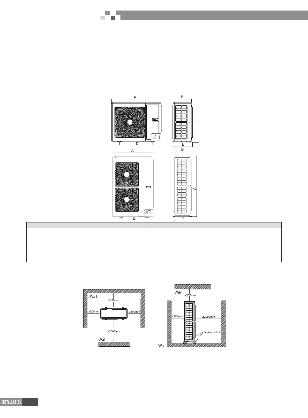
4.6 Outline dimension and position of installation hole
When carrying the outdoor unit, hang the unit in four directions with two sufcient ropes. In order to avoid excursion from the center, the
angel of ropes must be smaller than 40º during hanging and moving.
Model A B C D E
GMV-80WL/A-T
GMV-100WL/A-T
GMV-112WL/A-T
980 360 790 650 395
GMV-120WL/A-T
GMV-140WL/A-T
GMV-160WL/A-T
900 340 1345 572 378
4.7 Installation space requirement
If all sides of the ODU (including the top) are surrounded by walls, process according to the following requirements for installation
space:

 Loading...


