47
DC Inverter Multi VRF System II
Service Manual
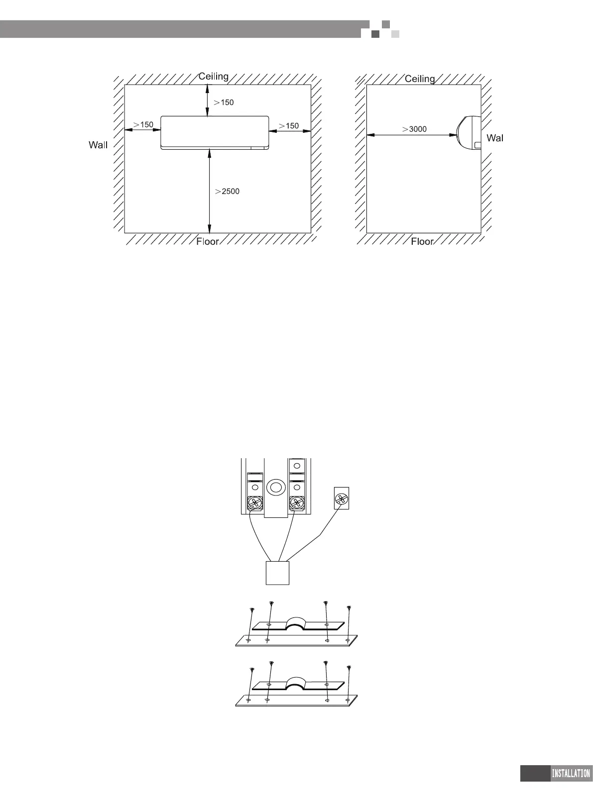
5.2.2 Installation space
5.2.3 Installation notice
(1) Installation dimension (refer to the outline dimension in the gure shown above)
(2) Installation foundation
Make sure the top hanger has sufcient strength to withstand the weight of unit.
(3) Installation site and environment
Keep the unit from insolation and rain;
Water can be drained from drainage pipe conveniently;
Keep the unit from re, ammable objects, corrosive gap or exhaust gas;
There can’t be any obstacle at air inlet and air outlet to in order to keep good ventilation;
Please reserve sufcient space for maintenance;
Please take proper measures to reduce noise and vibration.
5.2.4 Electrical installation of unit
(1) All electrical installation must be done by professionals according to national and local laws and regulations.
The unit must be grounded reliably according to related requirements in GB 50169.
Please connect wire according to the wiring diagram on the unit.
(2) External wiring diagram of unit
1) Description of power(including grounding) connection way
2) Description of power cord clamping device structure
3) Description of clamping device structure between function and connection cord

 Loading...


