54
DC Inverter Multi VRF System II
Service Manual
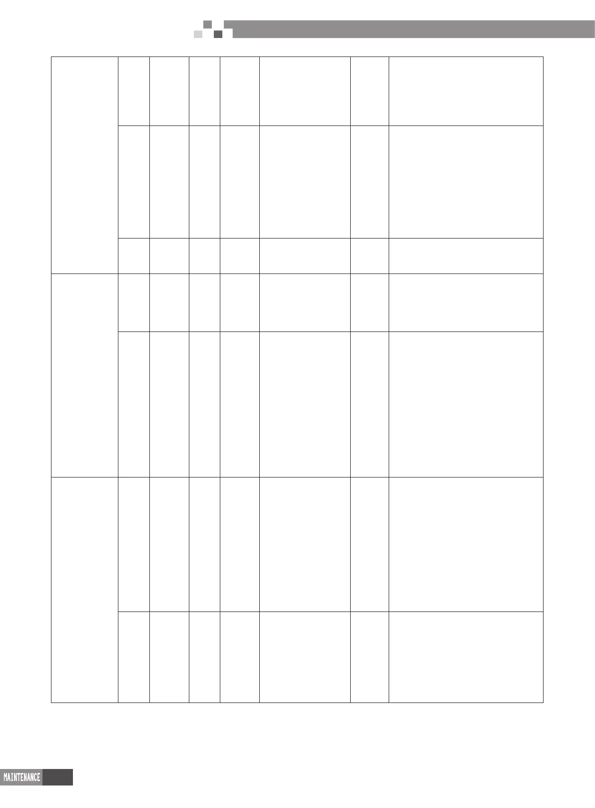
10_ Status
determination
for outdoor
unit’s valve
before startup
db ON 10 ON ON ON
Dermination status for valve of outdoor
unit; After compressor operating for
about 2min, it will stop operation. It
will judge the ON status of gas valve
and liquid valve for outdoor unit. The
judement result is displayed as below:
db ON 10 ON U6 ON
Valve for outdoor unit hasn’t been
opened completely. Short press SW6
button on main board and the indicator
will display “db 09 OC” and then check
whether gas valve and liquid valve for
outdoor unit are opened completely.
After that, short press SW6 button on
main board again. After compressor is
started up and operated for about 2min,
it will judge the status of valve again.
db ON 10 ON OC ON
Normal status for valve. After it displays
as the left method for 2s, it will enter into
the next determination automatically.
12_ Debugging
conrmation for
the unit
db ON 11 ON AP Flash
Wait for conrming the debugging order
for the unit. Short press SW7 button
on main bard to conrm the debugging
of unit. 2s later, the indicator on main
board will display as below:
db ON 11 ON AE ON
Conrmation of startup of the unit.
After displaying for 2s, the system
will select “15_cooling ddebugging
operation” or “16_heating debugging
operation”automatically according
ambient temperature to start up
operation. If it needs to add refrigerant
because of engineering requirement
while the refrigerant hasn’t been added
nished before debugging, refrigerant
can be added through low-pressure
detection valve during operation
process.
15_Debugging
operation for
cooling
db ON 15 ON AC ON
Debugging under cooling mode.
If there’s no malfunction after the
compressor operates for 30min, it
will enter into process 17 to nish
debugging; Or short press SW7 button
on main board during operation process
to conrm the completion of debugginig.
After conrmation, it will enter into
process 17 to nished debugging
compulsively. If there’s malfunction
during operation process, the display is
as below:
db ON 15 ON
Correspoding error
code
ON
There’s malfunction during debugging
process under cooling mode. After
removing all malfunctions, it will enter
into the next step determination. If the
outdoor unit is de-energized under
troubleshooting process, the unit will
enter into process 17 automatically after
energization to nishe debugging.

 Loading...


