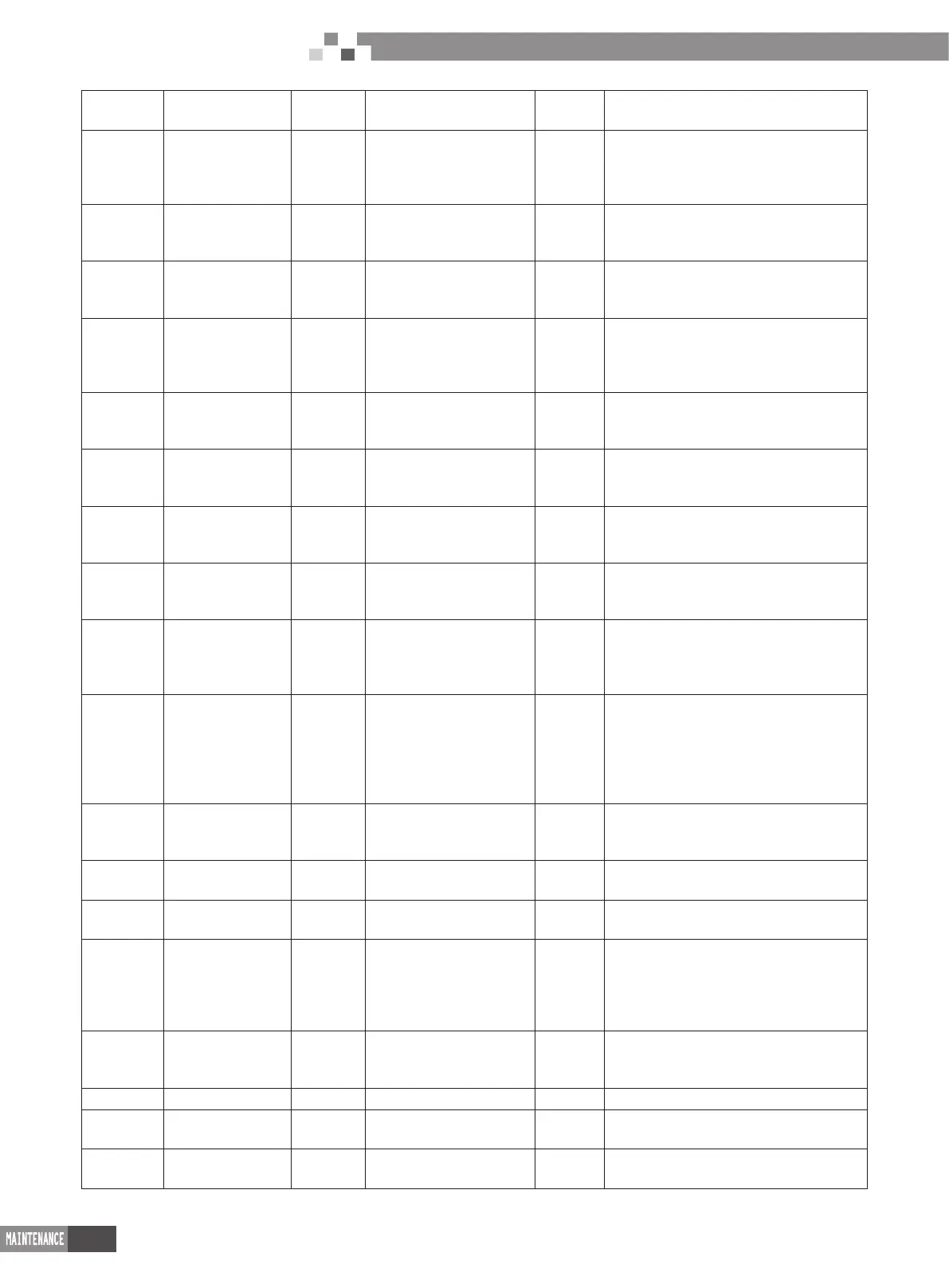
58
DC Inverter Multi VRF System II
Service Manual
bH
Abnormal clock of
system
P0
Malfunction driven board
for compressor
P1
Driven board of compressor works
abnormally
P2
Power voltage
protection for the
driven board of
compressor
P3
Reset protection for
the driven module of
compressor
P4 Driven PFC protection of compressor
P5
Overcurent
protection for
inverter compressor
P6
Driven IPM module
protection for compressor
P7
Malfunction of driven temperature sensor
for compressor
P8
Overheating
protection for driven
IPM of compressor
P9
Desynchronizing protection
for inverter compressor PH
High voltage protection for driven DC bus
bar of compressor
PC
Circuit malfunction
of driven current
detection for
compressor
PL
Low voltage protection
for driven DC bus bar of
compressor
PE Phase-losing of inverter compressor
PF
Malfunction of
driven charging loop
for compressor
PJ
Failure start up for inverter
compressor
PP
AC current protection for inverter
compressor
U0
Preheat time is
not enough for
compressor
U2
Capacity code of outdoor
unit/wrong setting of jumper
cap
U4 Insufcient refrigerant protection
U5
Wrong address for
the driven board of
compressor
U6
Alarm due to abnormal
valve
U8 Malfunction of pipeline for indoor unit
U9
Malfunction of
pipeline for outdoor
unit
UC
Setting for indoor unit and
oudoor unit is succeeded
UL
Wrong code-dialing during emergency
operation
UE
Refrigerant-
charging is invalid
C0
Communication malfunction
for indoor unit, outdoor
unit and wired controller of
indoor unit
C2
Driven communication malfunction between
main board and inverter compressor
C3
Driven
communication
malfunction
between main
board and inverter
compressor
C4
Malfunction of indoor unit-
lacking
C5
Alarming due to engineering series number
shock of indoor unit
C6
Alarming due to
wrong quanity of
outdoor unit
C8
Emergency status of
compressor
C9 Emergency status of fan
CA
Energycy status of
module
CH High rated capacity CC No malfunction of main control unit
CL Low rated capacity CF
Malfunction of main control
unit
CJ Address shock of syste
CU
Communication
malfunction
between indoor
unit receiving lamp
board
Cb
Distribution overow of Ip
address
A0 Debugging for unit
A1
Operational
parameter inquiry of
compressor
A2 Refrigerant recovery A3 Defrosting
A4 Oil return A5 On-line test A6 Heat pump function setting
A7 Quit mode setting A8
Vacuum pump
mode
A9 IPLV test
AA
EU AA class energy
efciency test mode
AH Heating AL Charge refrigerant automatically

 Loading...


