79
DC Inverter Multi VRF System II
Service Manual
that the pressure of governing valve hasn’t been increased.
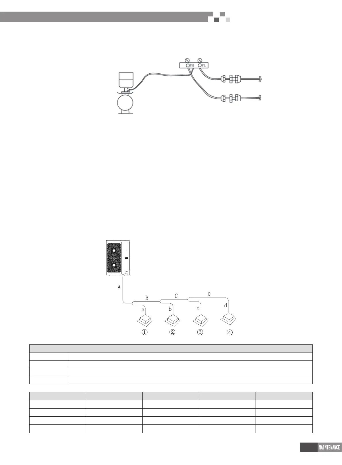
a .Vacuum pump for the gas pipe and liquid valve at the same time;
Connector on gas side
Connector on liquid side
Gas
liquid
Pressure gauge connector valve
Refrigerant cylinder
Spring balance
b .When turn off the vacuum pump to stop vacuum-pumping, please turn off the valve at rst and then de-energize the vacuum pump;
c .Keep the vacuum pump for 2h and conrm that the pressure of vacuum meter hasn’t been increased.
6.2 Fill and charge refrigerant
6.2.1 Filling procedure of regrigerant
a . Calculate the additional volume of refrigerant
Side discharge DC inverter and digital VRF (10KW above)
Additional volume of refrigerant R=LA×54 g
LA=L-50 m
L=(12.7 length of liquid pipe) × 2+(9.52 length of liquid pipe) ×1+(6.4 length of liquid pipe) ×0.4
When L is less than 50m, no need to add refrigerant
Other model:
Additional volume of refrigerant R=LA×54 g
LA=L-5m
L=(12.7 length of liquid pipe) × 2+(9.52 length of liquid pipe) ×1+(6.4 length of liquid pipe) ×0.4
When L is less than 50m, no need to add refrigerant
Examples:
ODU
IDU
Indoor unit
:
Model
Indoor unit Cassette type GMV-R71T/Na
Indoor unit Wall-mounted type GMV-R36G/Na
Indoor unit Super-slim duct type GMV-R50P/NaL
Indoor unit Duct type GMV-R25P/Na
Liquid pipe:
No. A B C D
Diameter of pipe φ9.52 φ9.52 φ9.52 φ6.35
Length 20m 10m 5m 5m
No. a b c d
Diameter of pipe φ9.52 φ6.35 φ6.35 φ6.35

 Loading...


