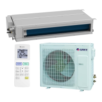
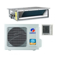
GREE COMMERCIAL AIR CONDITION A/A DC INVERTER U-MATCH AIR CONDITIONERS
1
CONTENTS
PRODUCT.................................................................................................................................................. 1
1 MODELS LIST................................................................................................................................ 2
1.1 Outdoor Unit.............................................................................................................2
1.2 Indoor Unit................................................................................................................3
2 NOMENCLATURE......................................................................................................................... 4
3 FUNCTION...................................................................................................................................... 5
4 PRODUCT DATA ...............................................................................................................6
4.1 Product Data at Rated Condition..............................................................................6
4.2 Operation Range ....................................................................................................19
4.3 Electrical Data ........................................................................................................20
5 PIPING DIAGRAM.......................................................................................................................21
CONTROL................................................................................................................................................23
1 OPERATION FLOWCHART ......................................................................................................23
1.1Cooling/Dry Operation.............................................................................................23
1.2 Heating Operation ..................................................................................................24
2 MAIN LOGIC.................................................................................................................................25
2.1 Cooling ...................................................................................................................25
2.2 Dry Mode................................................................................................................26
2.3 Heating Mode.........................................................................................................27
2.4 Defrosting...............................................................................................................28
2.5 Fan Mode ...............................................................................................................29
3 WIRELESS REMOTE CONTROLLER.....................................................................................30
3.1 Operation View.......................................................................................................30
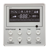
4 WIRED REMOTE CONTROLLER ............................................................................................33
4.1 Operation View.......................................................................................................33
4.2 Buttons ...................................................................................................................34
4.3 Installation of Wired Controller and Project Debugging ..........................................36
4.4 Instruction to Operation ..........................................................................................38
4.5 Error Display ..........................................................................................................50
4.5 Dimension ..............................................................................................................51
5 CENTRALIZED CONTROLLER................................................................................................52
5.1 Centralized Controller-not with week timer.............................................................52
5.2 Centralized Controller-week timer ..........................................................................53
5.3 Smart Zone Controller ............................................................................................55
INSTALLATION.......................................................................................................................................61
1 INDOOR UNIT INSTALLATION.................................................................................................61
1.1 Installation of Duct Type .........................................................................................61
1.2 Installation of Ceiling Type......................................................................................71
1.3 Installation of Cassette Type ..................................................................................75
2 OUTDOOR UNIT INSTALLATION............................................................................................84
2.1 Before Installation...................................................................................................84
2.2 Installation Site.......................................................................................................84
2.3 Caution for Installation............................................................................................85
2.4 Dimension Data......................................................................................................86
3 REFRIGERATION PIPING WORK ..........................................................................................86
3.1 Refrigeration Piping Work Procedures ...................................................................86
3.2 Caution in Connecting Pipes ..................................................................................89
3.3 Specification of Connection Pipe............................................................................91
4 ELECTRIC WIRING WORK.......................................................................................................91
4.1 Wiring Principle ......................................................................................................91
4.2 Electric Wiring Design ............................................................................................95
4.3 Specification of Power Supply Wire and Air Switch ................................................98
MAINTENANCE ....................................................................................................................................100
1 TROUBLE TABLE .....................................................................................................................100
2 FLOW CHART OF TROUBLESHOOTING............................................................................104
2.1 System Troubleshooting.......................................................................................104
2.2 Typical Troubleshooting for C series Outdoor Unit Drive (Inverter) by Single-phase
 Loading...