A/A DC INVERTER U-MATCH AIR CONDITIONERS CONTROL
36
4.3 Installation of Wired Controller and Project Debugging
4.3.1 Installation of Wired Controller
Fig.4.3.1: Fig.1
Surface mounting of Cable Fig.4.3.2: Fig.2 Concealed mounting of Cable
Fig.4.3.3: Sketch for Installation of Wired Controller
No. 1 2 3 4 5
Description
Socket’s base
box installed in
the wall
Soleplate of
controller
Screw M4X25
Front panel of
controller
Screw ST2.2X6.5
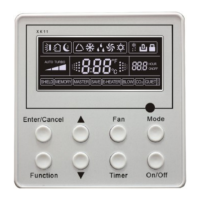
Fig.4.3.3: Sketch for Installation of Wired Controller. Pay attention to the following items during installation of wired
controller:
1. Cut off power supply of heavy-current wire embedded in mounting hole in the wall before installation. It is
prohibited to perform the whole procedure with electricity.
2. Pull out 4-core twisted pair line in mounting hole and then make it through the rectangle hole at the back of
controller’s soleplate.
3. Joint the controller’s soleplate on wall face and then fix it in mounting hole with screws M4X25.
4. Insert the 4-core twisted pair line through rectangle hole into controller’s slot and buckle the front panel and
soleplate of controller together.
5. At last, fix the controller’s front panel and soleplate with screws ST2.2X6.5.

 Loading...


