Air-to-water Heat Pump
37
MONOBLOC
TYPE
17. Wring Diagram
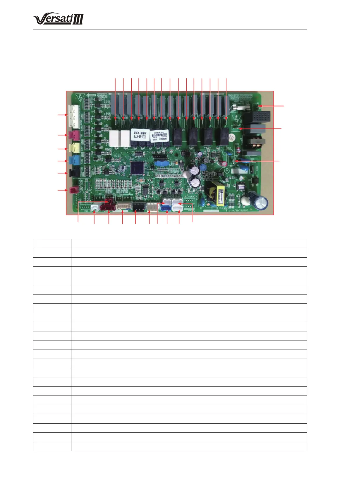
17.1 Control Board
(1) GRS-CQ4.0Pd/NhG-K, GRS-CQ6.0Pd/NhG-K, GRS-CQ8.0Pd/NhG-K
CN2CN1CN4CN3CN18
CN19CN15CN16
CN10
CN9
CN8
CN20
CN21
CN22
CN23
CN24
CN25
X27X28X29X30X31X32X33X34X20X21X22X23X24X25X26
N
AC_L
X3
Silk Screen Introduction
AC-L Live wire of power supply
N Neutral wire of power supply
X3 To the ground
X20 E-heater of water tank
X21 E-heater 1
X22 E-heater 2
X23 Assistant heat by 220VAC
X24 Reserved
X25 Electric heater for the plate-type heat exchanger
X26 Reserved
X27 Electric magnetic 2-way valve 1 is normally open
X28 Electric magnetic 2-way valve 1 is normally closed
X29 High-power load control
X30 High-power load control
X31 Electric magnetic 3-way valve 1 is normally open (reserved)
X32 Electric magnetic 3-way valve 1 is normally closed (reserved)
X33 Electric magnetic 3-way valve 2 is normally open (water tank)
X34 Electric magnetic 3-way valve 2 is normally closed (water tank)
CN30 Signals 1, 2, 3, 4, power supply 5
CN31 Signals 1, 2, 3, 4, power supply 5
CN18 Interface to the variable-frequency water pump
CN19 Interface to the variable-frequency water pump