7.
Reel Release Switch:
To release the dispenser for easily
taking out strapping from it.
8.
Foot Bar :
To initiate a strapping cycle.
To clear up machine fault. (reset)
9.
Foot Pedal Switch (Option):
To initiate a strapping cycle.
To clear up machine fault. (reset)
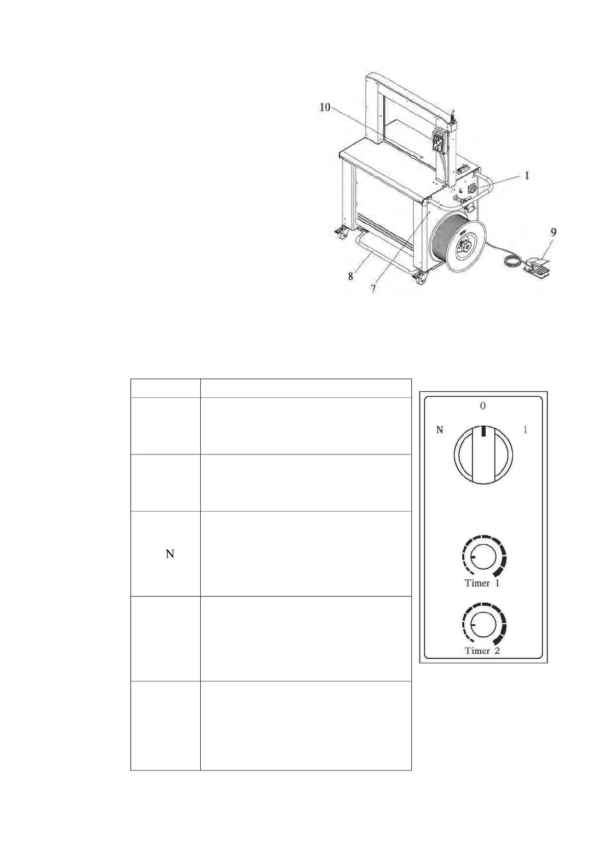
10.
Photo Eye Switch (Option)
The purpose of the photo-eye
switch is to automatically initiate strapping cycles when a package is detected.
The controls for the photo-eye are shown in the figure below.
Function Function
0
The photo-eye is disabled. The
strapping cycle must be initiated with
Start switch on the control panel or Foot
bar switch and optional foot pedal.
1
A single strapping cycle: initiates a
cycle when a package covers the
photo-eye. Delay time for initiating the
cycle is controlled by TIMER 1.
Multiple strapping cycles: initiates a
cycle when a package covers the
photo-eye. Cycling continuously until
the photo-eye no longer “sees” a
package. The cycle timing is determined
Timer 1
Sets the delay time from the moment
that a package is detected until the 1
st
strapping cycle initiates. This allows an
operator to properly position a package
for the first strap. It is adjustable from
Timer 2
It‟s the delay time (interval) between
strap cycles. When multiple strapping
cycles are needed, this timer is for an
operator to determine the interval
between each straps. It is adjustable
from zero to five seconds.