3
These instructions apply to 1
1
/2 and 3 hour rated combination fire smoke dampers mounted (blades must be horizontal) in:
1) masonry, block or stud walls and 2) concrete floors or ceilings. Specific requirements in these instructions are mandatory.
Dampers must be installed in accordance with these instructions to meet the requirements of UL 555 and UL 555S. The
installation of the damper and all duct connections to the damper sleeve shall conform to the latest editions of NFPA 90A,
Standard for the Installation of Air Conditioning and Ventilating Systems, and the SMACNA Fire, Smoke and Radiation
Damper Installation Guide, and U.L. Classifications R13317.
1. CLEARANCES REQUIRED BETWEEN FIRE DAMPER SLEEVES AND WALL/FLOOR OPENINGS
Fire damper and sleeve assemblies expand during periods of intense heat. Therefore, it is essential that openings
in walls or floors be larger than the fire/smoke
damper and sleeve assembly to
allow for this expansion. Minimum
clearances required between the
outside of fire damper sleeve
assemblies and wall/floor
openings are:
• Galvanized steel fire
dampers and sleeves:
1
⁄8
in. per foot of damper
width and height with a
minimum clearance of
1
⁄4 in., maximum of 1
1
⁄2
in.
Recommended
clearances, for
width and/or height
dimensions of:
1) 48 in. or less:
1
⁄2 in.
clearance
2) More than 48 in. and 96
in. or less: 1 in. clearance
3) More than 96 in.: 1
1
⁄2 in.
clearance
• Stainless steel fire/smoke
dampers and stainless steel or
galvanized sleeves:
3
⁄16 in. per foot of
damper width and height with a minimum
clearance of 1/4 in., maximum of 2 in.
Recommended clearances, for width and/or height dimensions of:
1) 48 in. or less:
3
⁄4 in. clearance
These are total clearances (ignoring fastener heads) and do not need to
be equally spaced around the damper. Refer to Section 4 and Figure 6 for
additional installation considerations.
SAFETY DANGER !
Electrical input may be needed for
this equipment. This work should be
performed by a qualified electrician.
All wiring shall be done in accordance with the National
Electrical Code ANSI/NFPA-70 latest edition, any local codes
that may apply, and wiring diagrams developed in compliance
with the job or project design and specifications.
Electrical Guidelines
Installation - Failure to follow these instructions will void all warranties.
SAFETY CAUTION !
Verify power before wiring actuator. Greenheck is not responsible for any damage to, or failure of
the unit caused by incorrect field wiring.
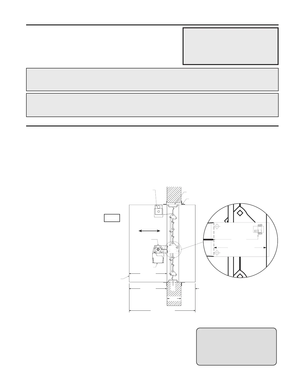
0QUJPOBMCMBEFJOEJDBUPS
BOEPSFMFDUSJDMJOL
,).%/&7!,,
$/./4).34!,,3#2%7 3
"%47%%.4(%3%,).%3
!2/5.$%.4)2%$!-0%2
$MFBSBODFGPSFYQBOTJPO
JONJOJONBY
3FUBJOJOH"OHMFT
TFF4FDUJPO
-*OFPG8BMM
"JSnPX
%FUBJM
%0/05*/45"--4$3&84
#&58&&/5)&4&-*/&4
"306/%&/5*3&%".1&3
"DDFTTEPPSSFRVJSFEPO
KBDLTIBGUTJEFPGEBNQFS
3FGFSUPUIFMBUFTUFEJUJPO
PG/'1""
+BDLTIBGU
"DUVBUPS
%BNQFS
4MFFWF
4MFFWF-FOHUI-
JONBY
JONBY
A"%JN
%JTUBODFGSPN
FOEPGTMFFWFUP
GBDFPGEBNQFS
5
X
$
-
Example: A 12 in. x 12 in. damper
will require a minimum
clearance of
1
/4 in.
A 36 in. x 12 in. damper
will require a minimum
clearance of
1
/2 in. on width
and
1
/4 in. on height.
Dampers may be mounted either vertically or
horizontally. Blade axis must always be horizontal.
SAFETY DANGER ! : To avoid causing death or serious bodily harm to building occupants, follow
all instructions carefully. Dampers must close completely to preserve the
integrity of the fire smoke separation.
Fig. 1