Maximum Max Overall Size
Damper
Single-Section for Multi-Section
Model Size Dampers
DFD-230 36
x 36 or 32 x 48 64 x 48
DFD-210 36 x 36 or 32 x 50 64 x 50
DFDTF-210 32 x 36 96 x 72
DFDTF-210 32 x 50 64 x 50
FSD-211, 212, 213 36 x 48 or 32 x 50
FSD-311,311M, IMO-311 32 x 50
FSD-312, 312M 32 x 50
IMO-311 32 x 36
FSD-231 36 x 36 or 32 x 48 72 x 48
SEFSD-211/SEDFD-210 24 x 30 48 x 30
SSFSD-211/SSDFD-210 24 x 30 48 x 30
IMO-310,DFDAF-310 32 x50 NA
NOTE: FSD model dampers fitted with a fusible link
closure device are limited to single section sizes.
Dampers with a fusible link and spring assembly closure
device may not be used for multiple section applications.
The damper sections must be attached together with #10
(
3
/4 in. max.) sheet metal screws,
1
/4 in. diameter nuts and
bolts, tack or spot welds, or
3
/16 in. diameter steel pop
rivets. Attachments must be spaced a minimum of 6 in.
on centers and a maximum of 2 in. from corners. (see
Fig. 3) Attachments must be made on front face and
back face (air entering and air exiting side) of damper
sections.
5
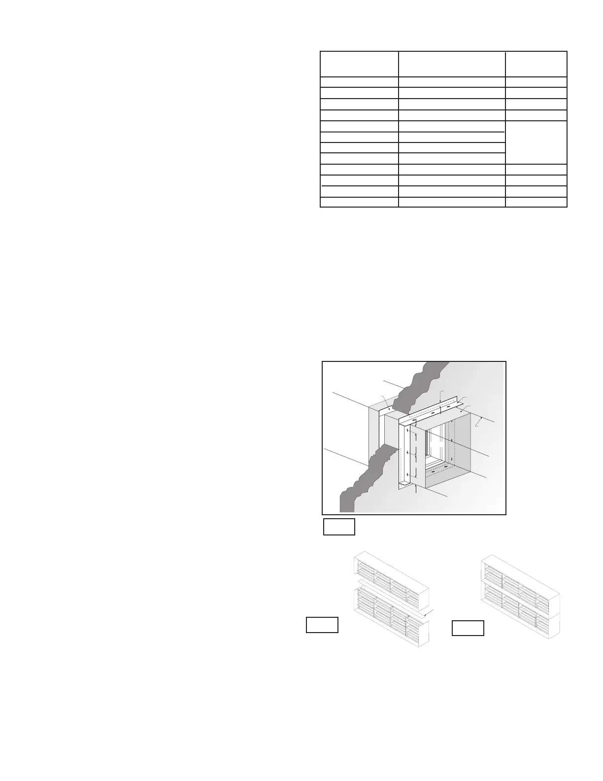
4. SECURING THE DAMPER/SLEEVE ASSEMBLY
TO WALL AND FLOOR OPENINGS (continued)
A minimum of two connections per side, top, and
bottom, 12 in. O.C. maximum for openings of 48 in. W
x 36 in. H and less, and 6 in. O.C. for openings 80 in. W
x 50 in. H, 50 in. W x 72 in. H, and 40 in. W x 72 in. H or
less. The angles must be attached to all 4 sides of the
sleeve. Ensure that attachment device does not interfere
with the operation of the damper and the free movement
of the damper blades. The angles need not be attached
to each other at the corners. Do not secure the retaining
angle to the fire separation.
• Retaining angles must completely cover the
clearance space between the damper and the
wall/floor opening, plus overlap the wall/floor
a minimum of 1 in. This coverage includes all
corners.
• Retaining angles should not be fastened to
the wall/floor material. The angles should only
sandwich the wall/floor and allow for damper
expansion during periods of intense heat.
5. ACTUATOR CONNECTIONS
Electrical and/or pneumatic connections to damper
actuators should be made in accordance with wiring and
piping diagrams developed in compliance with applicable
codes, ordinances and regulations (see Electrical
Guidelines).
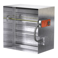
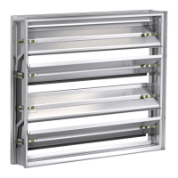
6. INSTALLING MULTIPLE DAMPER SECTION
ASSEMBLIES
A damper assembly is not restricted to a maximum
number of sections, but must not exceed the section
sizes and overall sizes shown (see chart).
Two section high dampers require reinforcement using a
14 gauge, 5 in. wide mullion as shown in Figure 4 below,
or two individually sleeved units stacked vertically, shown
below in Figure 5. When using two individually sleeved
units, the sleeve acts as the mullion, therefore no mullion
is required.
Note: Dampers ordered for individual installation may
not be installed together. The full assembly size must be
specified at the time the dampers are ordered.
7. CONNECTION AND OPERATION OF
TEMPERATURE RESPONSE DEVICES (RRL
STANDARD, OCI OPTION, AND TOR OPTION)
RRL - Dampers will be supplied with a thermostat-type
temperature response device, as a standard. The device is
a RRL (resettable link device), which only incorporates one
thermostat and therefore the damper remains closed as
soon as its sensor temperature is reached. The RRL does
not contain blade indication switches. Refer to Figure 6 for
wiring of the RRL thermostat.
OCI - The OCI (open or closed indicator) option contains
a single pole, double throw switch used to indicate the
damper blade position. The switch provides a positive open
or closed signal when used in conjunction with remote
indicator lights. Refer to Fig. 7 for wiring of the OCI option.
Vertical Mount
IN
-
AX
IN
-
AX
3LEEVE
2ETAINING
!NGLE
$AMPER
$UCT
-ININ
/VERLAP
7ALLOR
&LOOR
2ETAINING
!NGLE
ONLYAPPLICABLEFORDAMPERSIZESABOVEINXIN
IN
-
AX
IN
-
AX
Both vertical and horizontal damper installations are typified by these drawings.
Fig. 3
128 x 100
GA
INWIDE
3UPPORT
-ULLION
Fig. 4
Fig. 5
Single Sleeve Around
Outside with Support
Mullion
Two Individually Sleeved
Units with No Mullions