Pre-Installation Guidelines
The basic intent of a proper installation is to secure the fire smoke damper in, not to, the opening in such a manner as to
prevent distortion and disruption of damper operation. This is accomplished by allowing the fire smoke damper in rated
separation openings to expand and for the connecting duct to separate in the event of the collapse of the hanging system.
The following items will aid in completing the damper installation in a timely and effective manner.
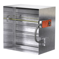
1) Check the schedules for proper damper locations within the building. Visually inspect the damper for damage and verify
that the Reusable Resettable Link (RRL) is in place or has not activated. Never install a fire damper without the proper
UL approved RRL in place. (RRL is standard control option. These electric links have a button for resetting.)
2) Lift or handle damper using sleeve or frame. Do not lift damper using blades or actuators.
3) Damper has label on outside of sleeve indicating a ‘No Screw’ area. Do not install screws into this area as screws may
interfere with unexposed blade linkage and prevent damper blades from opening and/or closing.
4) Damper has label indicating position of damper and sleeve assembly in the wall. Install accordingly to comply with
manufacturer’s appropriate UL Classification file number.
5) Damper must be installed into duct or opening square and free of twist or other misalignment. Damper must not be
squeezed or stretched into duct or opening. Out of square, racked, twisted or misaligned installations can cause
excessive leakage and/or torque requirements to exceed damper/actuator design.
6) Damper and actuator must be kept clean and protected from dirt, dust and other foreign materials prior to and after
installation. Examples of such foreign materials include but are not limited to:
a) Mortar dust
b) Drywall dust
c) Firesafing materials
d) Wall texture
e) Paint overspray
7) Damper should be sufficiently covered as to prevent overspray if wall texturing or spray painting will be performed
within 5 feet of the damper. Excessive dirt or foreign material deposits on damper can cause excessive leakage and/or
torque requirements to exceed damper/actuator design.
8) Caulking is not necessary, nor is it allowed, between the damper sleeve and the wall or floor opening (annular space).
However, caulking may be applied to the retaining angles.
9) ACCESS: Suitable access (such that RRL’s and actuators can be maintained, etc.) must be provided for damper
inspection and servicing. Where it is not possible to achieve sufficient size access, it will be necessary to install a
removable section of duct. (Refer to NFPA 90A).
10) The Code Authority Having Jurisdiction (AHJ) must evaluate and provide approval of final installation where variations to
these instructions are necessary.
2
Table of Contents
Pre-Installation Guidelines ...................................................................................2
Electrical Guidelines .............................................................................................3
Installation .........................................................................................................3-8
•
Clearances Required Between Fire Damper Sleeves and Wall/Floor Openings .......3
•
Sleeve Length and Wall Thickness .................................................................4
• Duct to Sleeve Connections ........................................................................4
• Securing the Damper/Sleeve Assembly to Wall and Floor Openings .....................5
•
Actuator Connections ...................................................................................5
• Installing Multiple Damper Section Assemblies.................................................5
•
Connection and Operation of Temperature Control Devices.............................5-6
• Recommended Preparation of Openings in Wood and Metal Stud Walls ...........6-7
• Breakaway Connections ...........................................................................7-8
Maintenance .........................................................................................................8
Troubleshooting ....................................................................................................8