6
RATINGS
Integral Switch Type: Single Pole, double throw
Electrical Capacity: 10 Amps,
1
/3 hp, 120 or 240 Vac
1
/2 Amp, 125 Vdc;
1
/4 Amp 250 Vdc
5 Amps, 120 Vac “L”
(lamp load)
1.0 Amps, 24 Vac
1.5 Amps, 24 Vdc
Temperature Limit: 165°
F (standard primary sensor)
212°
F (optional primary sensor)
250°
F (secondary sensor)
350°
F (secondary sensor)
RATINGS (Fig. 8)
Integral Switch Type: Single Pole, double throw
Electrical: 10 Amps,
1
/3 hp, 120 or 240 Vac
1
/2 Amp, 125 Vdc;
1
/4 Amp 250
Vdc 5 Amps, 120 Vac “L” (lamp
load)
1.0 Amps, 24 Vac
1.5 Amps, 24 Vdc
Temperature Limit: 165° F (standard primary sensor)
212°
F (optional primary sensor)
250°
F (secondary sensor)
350º F ( secondary sensor)
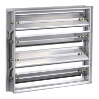
L1
DAMPER
INDICATOR
LIGHTS
ELECTRIC DAMPER
ACTUATOR OR PNEU. SOLENOID
VALVE
M
L2
BROWN
YELLOW
YELLOW
ORANGE
HL=HIGH LIMIT SENSOR
P=PRIMARY TEMP SENSOR
OR = OVERRIDE
OR
ON
OFF
BY OTHERS
WHITE
NC
YELLOW
YELLOW
S1
S2
NO
NO
P
NC
BROWN
HL
BLACK
CLOSED POSITION OF THE DAMPER.
A BLUE MARKER INDICATE THE
THE SWITCH WIRES WRAPPED WITH
ELECTRICAL CAPACITY = 10AMP @ 120 / 240 VAC
NOTE:
OPEN-CLOSED INDICATOR
TEMPERATURE LIMITED OVERRIDE/
TOR Wiring
Fig. 8
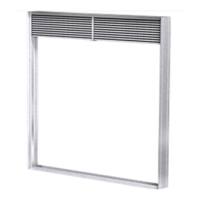
-ETAL3TUD#ONSTRUCTION
7OODEN3TUD#ONSTRUCTION
)NWOODSTUDCONSTRUCTION
GYPSUMWALLBOARDMUSTCOVER
ALLWOODSTUDSURFACES
'YPSUM 7A LLBOARD
3TUDOR2UNNER
2ETAINING
!NGLE
IN-IN
$AMPER
3LEEVE
)NMETALSTUDCONSTRUCTION
EXPOSEDSTEELSURFACESNEED
NOTBECOVERFEXJUIHZQTVN
WALLBOARD
'YPSUM 7ALLBOARD
3TUDOR2UNNER
2ETAINING
!NGLE
IN-IN
$AMPER
3LEEVE
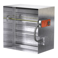
L1
DAMPER
INDICATOR
LIGHTS
L2
CLOSED POSITION OF THE DAMPER.
A BLUE MARKER INDICATE THE
THE SWITCH WIRES WRAPPED WITH
NOTE:
YELLOW
ELECTRICAL CAPACITY = 10AMP @ 120 / 240 VAC
YELLOW
YELLOW
YELLOW
NO
NO
S2
S1
BY OTHERS
OCI Wiring
Fig. 6
Fig. 7
L1
M
L2
ELECTRIC DAMPER
ACTUATOR OR PNEUMATIC
SOLENOID VALV E
PRIMARY TEMP
SENSOR
ELECTRICAL CAPACITY = 10 AMP @ 120 / 240
VA
C
BLACK
ORANGE
P
NC
BLACK
WHITE/RED
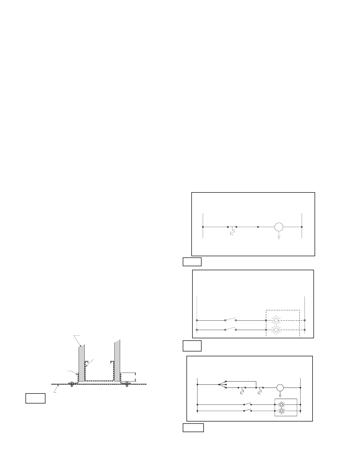
RRL Wiring
Fig. 9
7. CONNECTION AND OPERATION OF TEMPERATURE
RESPONSE DEVICES (continued)
TOR - The TOR (temperature override device) option
incorporates two thermostats with fixed settings (usually 165°F
and 350°F). The primary sensor (the sensor with the lower
temperature setting) can be bypassed by an external electrical
signal allowing the damper to reopen until the temperature
reaches the setting of the secondary sensor (the sensor with
the higher temperature setting). See Figure 8.
When the temperature of the secondary sensor is exceeded the
damper closes and remains closed thereafter.
The TOR assembly also contains a single pole, double throw
switch used to indicate damper blade position. The switch
provides a positive open or closed signal when used in
conjunction with remote indicator lights. See Fig. 8 for wiring of
the TOR thermostats and indicator switches.
If either the TOR or the RRL is ordered with a pneumatic
actuator, an EP switch is required with an appropriate electric
power circuit to allow the electric thermostat to control the
pneumatic actuator.
PRV - The PRV (pneumatic relief valve) option is heat
responsive device used with pneumatic actuators. This can
be used in place of EP switch where a RRL is used. The PRV
activates when temperature in excess of the temperature of the
fusible link are detected. When the fusible link melts, air from
the actuator is exhausted to close the dampers. Pneumatic
actuators are to be piped per local code.
8. Recommended Preparation of Openings in Wood
and Metal Stud Walls
• Frame wall openings as shown below. (see Fig. 9 & 10)
• Double vertical studs are not required for openings 36 in. x
36 in. or smaller.
• Gypsum wall board must be fastened 12 in. on center to
all stud and runner flanges surrounding opening.
(see Fig. 11)
• All construction and fasteners must meet the requirements
of the appropriate wall design (See UL Fire Resistance
Directory) and/or local codes.