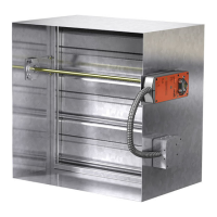
0LAINh3v3LIP (EMMEDh3v3LIP$OUBLEh3v3LIP
)NSIDE3LIP*OINT3TANDINGh3v3TANDINGh3v!LT
3TANDINGh3v!LT3TANDINGh3v3TANDINGh3v
"AR2EINFORCED !NGLE2EINFORCED
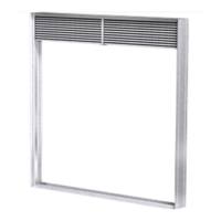
Do not bolt corners
Fire Damper Sleeve
(Attach per
manufacturer’s
instructions)
Duct
Neoprene gasket
between all angles
Flanged system angles
6 in. long 1/16 in. max.
thickness plastic cleats;
12 in. c-c (min. 1 per side)
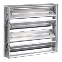
Traditional Breakaway Style Transverse Joints
Transverse joints illustrated at right have always
been approved as breakaway connections.
• The breakaway connections shown to the right
can be applied maximum of (2) #10 sheet metal
screws on each side and on the bottom located
in the center of the slip pocket and penetrating
both sides of the slip pocket.
• Transverse joints illustrated can be applied as
top and bottom joints with Drive Slip - side
joints in duct heights up to 20 inches.
Round and Oval Duct Breakaway Connections
Round or flat oval ducts connected to Type R or O damper collars shall be attached with #10 sheet metal screws
as follows:
• Ducts to 22 in. wide (or dia.) and smaller shall have three screws.
• Ducts larger than 22 in. wide (or dia.) up to and including 36 in. wide (or dia.) shall have five screws.
NOTE: All breakaway connections described may have duct sealant, PA2084T Duct Sealant Adhesive manufactured by Precision,
DP1010 water base duct sealant manufactured by Design Polymetrics or Grey Pookie, applied in accordance with SMACNA
recommendations.
Manufactured Flanged System
Breakaway Connections
Flanged connection systems manufactured
by Ductmate, Ward, and Nexus are approved
as breakaway connections when installed as
illustrated.
Fig. 13
Fig. 12
Fig. 14
9. Breakaway Connections
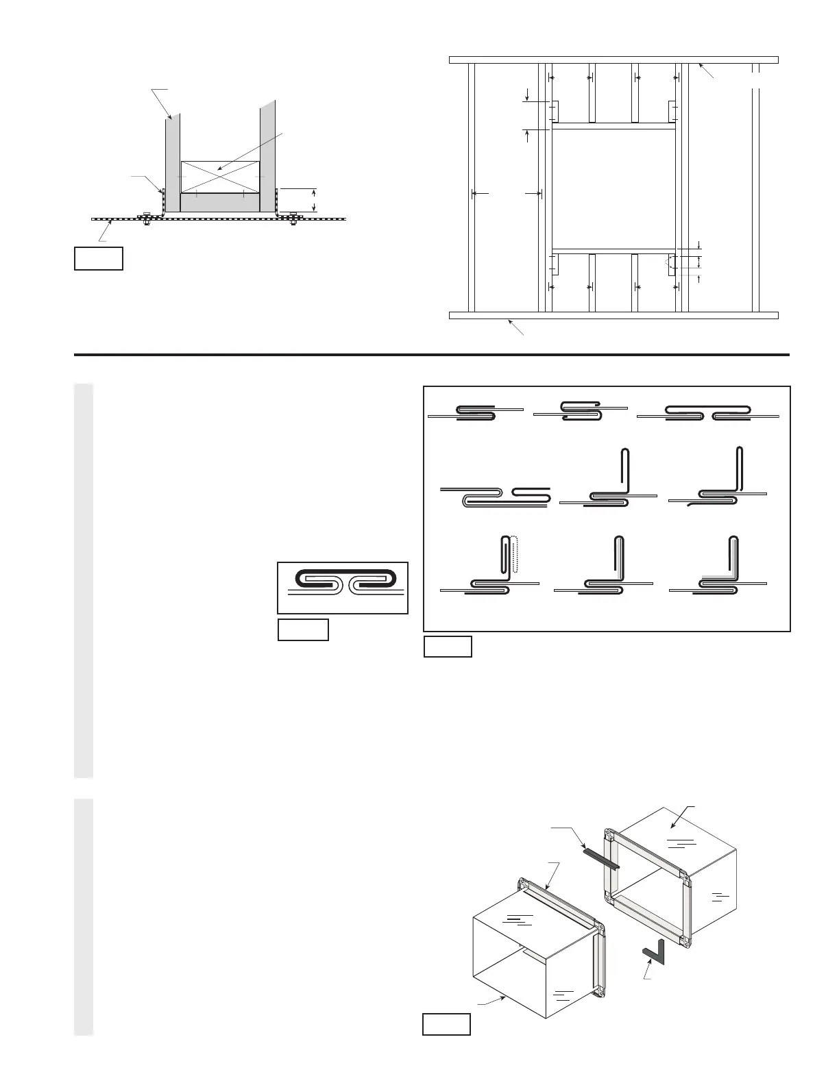
.FUBM4UVE$POTUSVDUJPO
8PPEFO4UVE$POTUSVDUJPO
*OXPPETUVEDPOTUSVDUJPO
HZQTVNXBMMCPBSENVTUDPWFS
BMMXPPETUVETVSGBDFT
(ZQTVN8BMMCPBSE
4UVEPS3VOOFS
3FUBJOJOH
"OHMF
JO.JO
%BNQFS
4MFFWF
*ONFUBMTUVEDPOTUSVDUJPO
FYQPTFETUFFMTVSGBDFTOFFE
OPUCFDPWFSFEXJUIHZQTVN
XBMMCPBSE
(ZQTVN8BMMCPBSE
4UVEPS3VOOFS
3FUBJOJOH
"OHMF
JO.JO
%BNQFS
4MFFWF
Fig. 10
TraditionalManufactured
JO
JOPD
.BYJNVN
'MPPS3VOOFS
$FJMJOH3VOOFS
JOPD
.BYJNVN
NFUBMTUVET
JOPD
.BYJNVN
NFUBMTUVET
JOPD
.BYJNVN
XPPETUVET
JOPD
.BYJNVN
XPPETUVET
JONN
JONN
1BOIFBE
4DSFXT
7