Symptom Possible Cause Corrective Action
Frame is ‘racked’ causing blades to Adjust frame such that it is square
bind on jamb seals and plumb
Actuator linkage loose Close damper, disconnect power, adjust
and tighten linkage
Defective motor Replace
Screws in damper linkage Locate screws and remove
Actuator linkage hitting wall or floor Damper installed too far into wall. Move
out to line designated on damper label.
Contaminants on damper Clean with a non-oil-based solvent
(see Damper Maintenance)
Copyright © 2005 Greenheck Fan Corporation
IOM 461336 FSD Rev. 8 May 2005
Damper does not
fully open and/or
fully close
Damper does not
operate
RRL or TOR sensor
tripped
Heat
No power supplied to the actuator
Push reset button located on backside
of RRL or TOR.
Damper Trouble Shooting
The following is a possible cause and correction list for common concerns with the dampers.
Damper Maintenance
Dampers do not typically require maintenance as long as they are kept dry and clean. If cleaning is necessary,
use mild detergents or solvents. If lubrication is desired for components such as axle bearings, jackshaft
bearings and jamb seals, do not use oil-based lubricants or any other lubricants that attract contaminants such
as dust.
Dampers and their actuator(s) must be maintained, cycled, and tested a minimum of every six months and in
accordance with:
• The latest editions of NFPA 90A, 92A, UL864, and local codes.
• Actuator manufacturer recommendations.
$UCT
3LEEVE
IN
3TD#LIP
,ENGTH
#
,
$UCT
IN$UCT
2EQD
IN$UCT
2EQD
IN$UCT
2EQD
IN$UCT
2EQD
IN$UCT
3MALLER
2EQD
#LIP3PACING
4YPICAL4$#4$&JOINT
IN IN
IN
ININ
IN IN
ININ
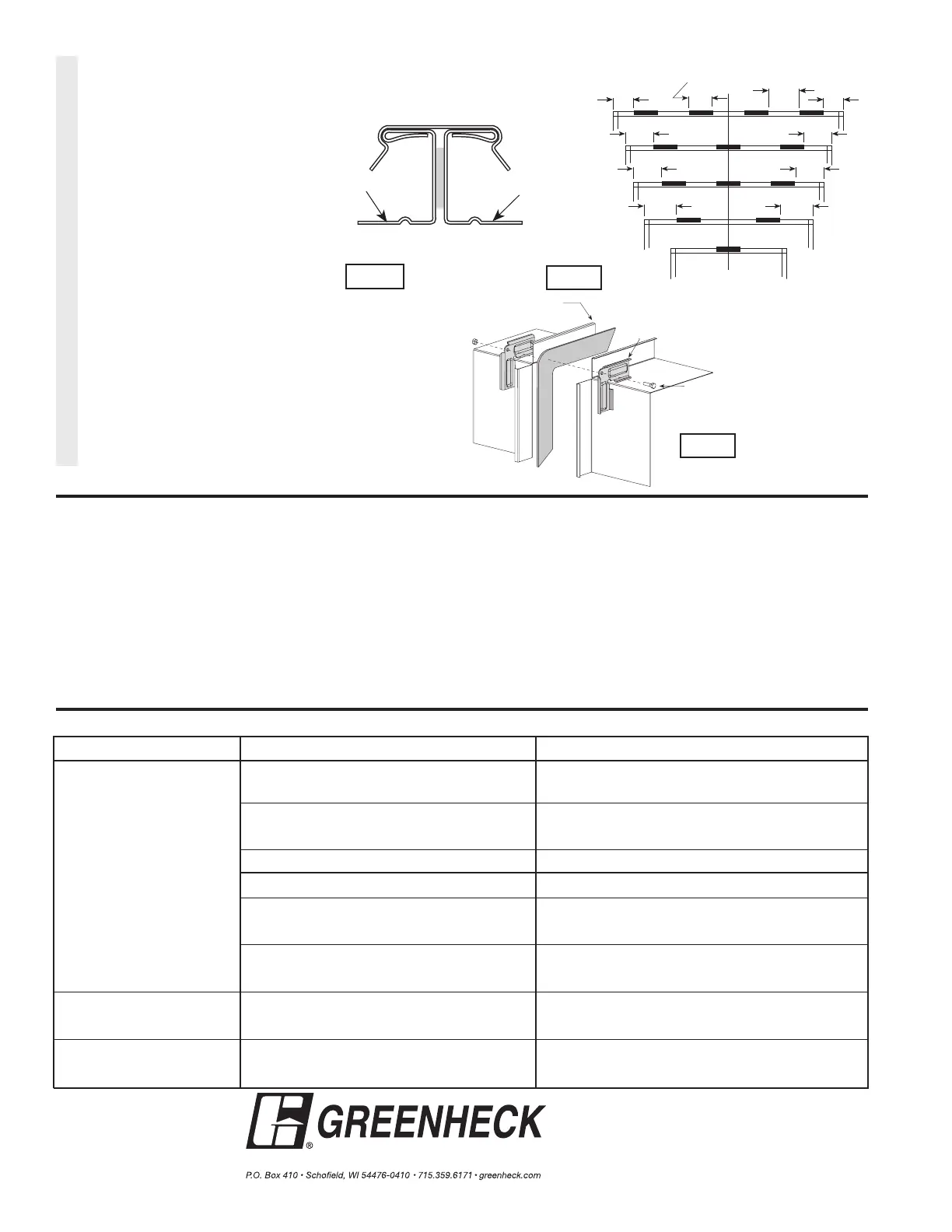
Proprietary Flange System
Breakaway Connections
(TDC by Lockformer, TDF by Engle)
TDC and TDF systems are approved
as breakaway connections when
installed as described in the TDC or
TDF addendum to the SMACNA Duct
Construction. Standard 6 in. metal clips
may be used with spacing as shown in
diagram. 3/8 in. metal bolts and nuts
may be used to fasten together corner
pieces (see Figure17).
Fig. 16
Fig. 15
Proprietary
$UCT%ND
&LANGE
#ORNER0IECE
INBOLT
OPTIONAL
Fig. 17