Unit Size A B
ERV-90 4.63 32
ERV-120 4.88 33.25
All dimensions are in inches.
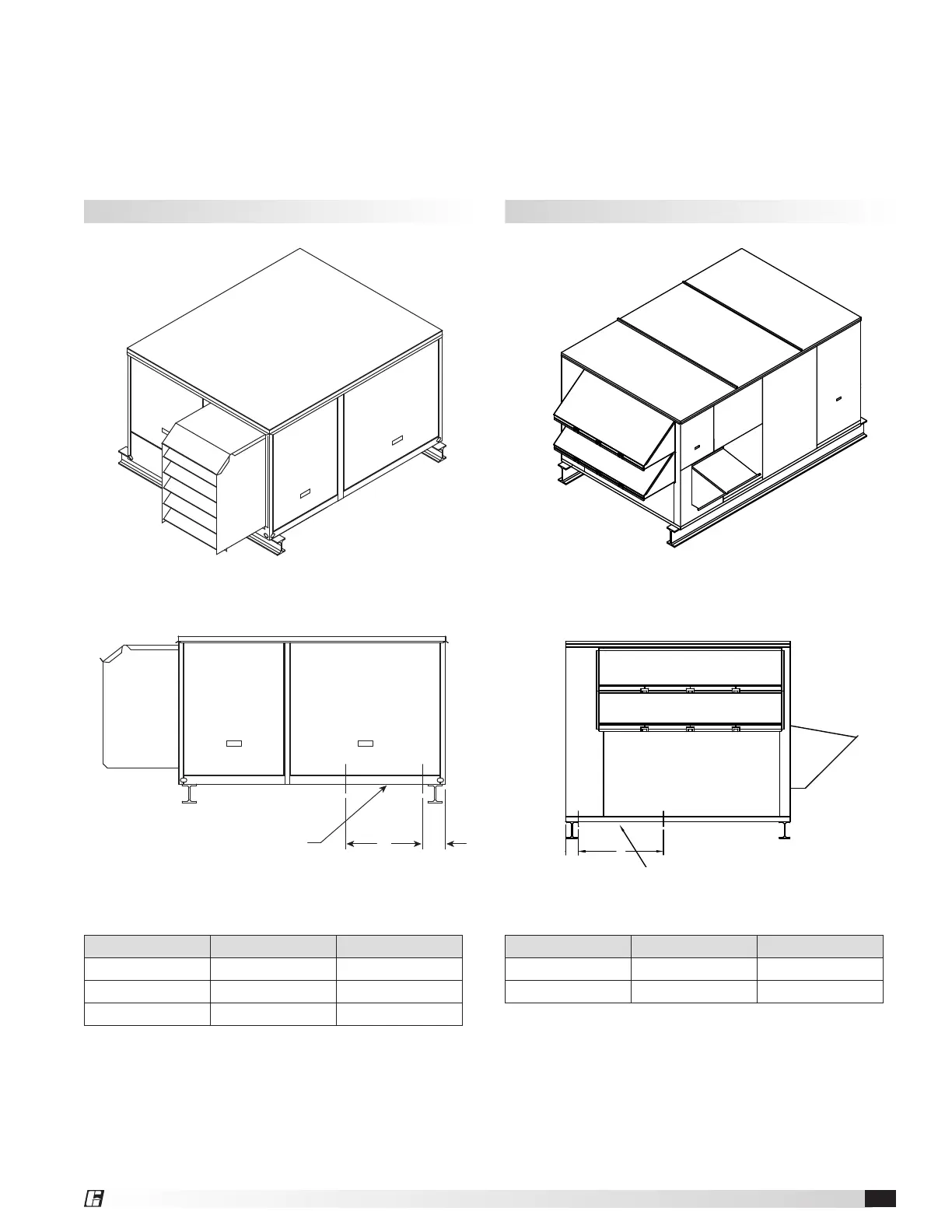
Isometric view of ERV on rails
Side view of ERV on rails
Unit Size A B
ERV-10 4.50 16
ERV-20 4.75 18
ERV-45 5.75 24
All dimensions are in inches.
Rail Mounting / Layout
1. Rails designed to handle the weight of the ERV should be positioned as shown on the diagram (rails by others).
2. Make sure that rail positioning does not interfere with the supply air discharge opening or the exhaust air intake
opening on the ERV unit. Avoid area dimensioned “B” below.
3. Rails should extend beyond the unit a minimum of 12 inches on each side.
4. Set unit on rails.
ERV-10, ERV-20 and ERV-45 ERV-90 and ERV-120
B A
SUPPLY/EXHAUST
OPENINGS
(OPTIONAL)
Isometric view of ERV on rails
Side view of ERV on rails
A B
SUPPLY/EXHAUST
OPENINGS
(OPTIONAL)
B A
SUPPLY/EXHAUST
OPENINGS
A B
SUPPLY/EXHAUST
OPENINGS
(OPTIONAL)
Energy Recovery Ventilator 11
 Loading...