11
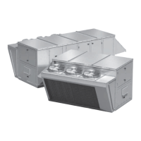
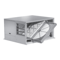
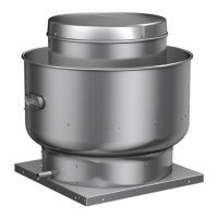
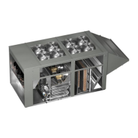
Packaged Rooftop Ventilator
Control Center Components
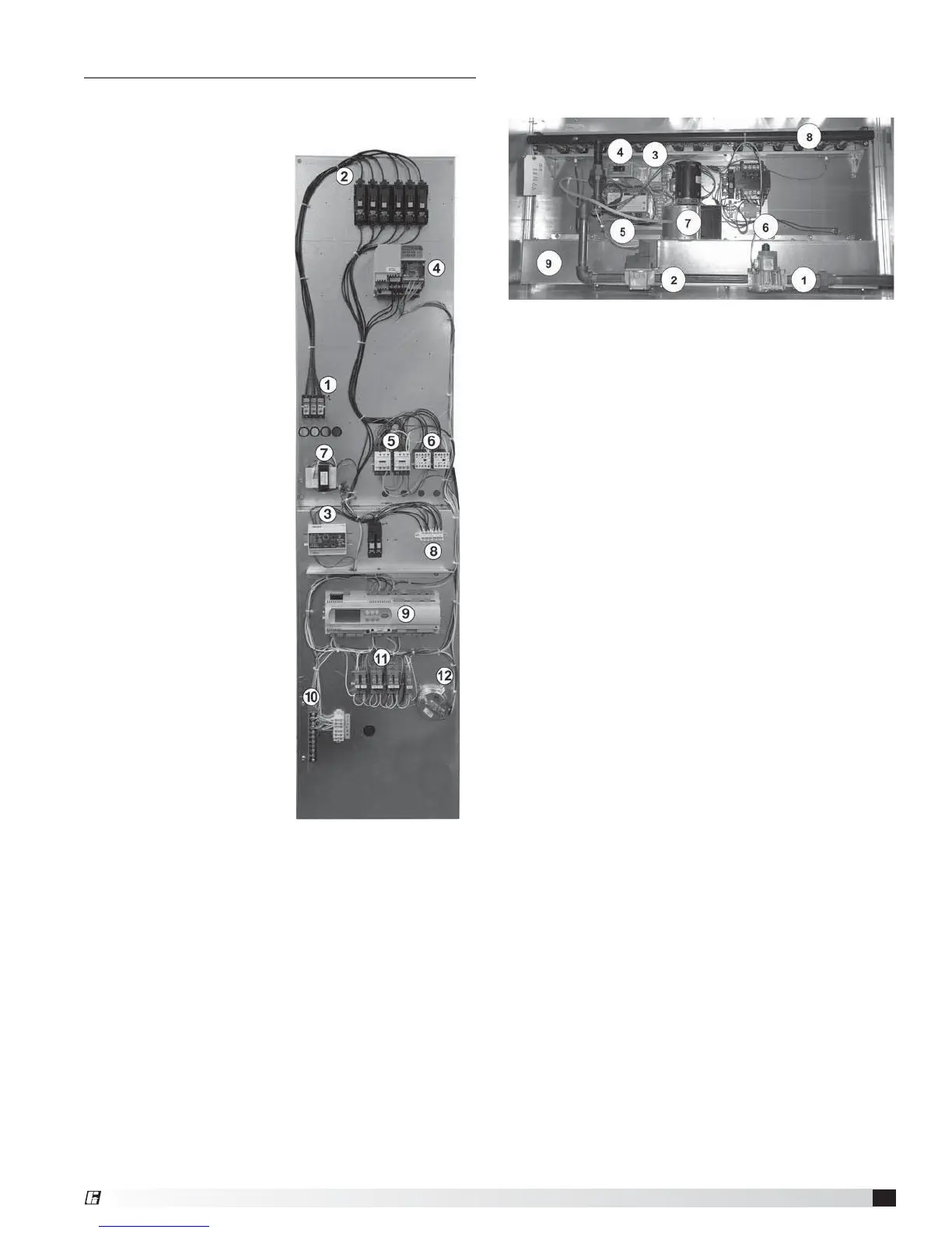
Main Control Center Components
This is a typical installation. Components and their
locations will vary.
High Voltage Side
1. Power Distribution
Block (high voltage
supply is terminated
here).
2. Fuse Holders
3. Phase Monitor
4. VFD
5. Compressor Motor
Contactors
6. Condensing Fan
Motor Contactors
7. Transformer
8. Terminal Strip
Low Voltage Side
9. DDC Controller
10. Low Voltage
Terminal Strip
11. Relays
12. Dirty Filter Switch
Optional Indirect Gas-Fired Furnace
Note: In some models, two furnaces are installed to
provide greater output. When two furnaces are installed,
they are in parallel and both will operate at the same
time and the same output. Both furnaces will have
identical controls.
1. Single-Stage Valve
2. Modulating Valve
3. Input Converter
4. FX Controller (modulates heat and switches entire
unit on/off)
5. Spark Generator (has high voltage present)
6. Transformer
7. Combustion Blower
8. Burner Manifold
9. Collector Box
For further information on the optional furnace and its
control center, see the Indirect Gas-Fired Heat lOM
shipped with the unit.
®
 Loading...