13
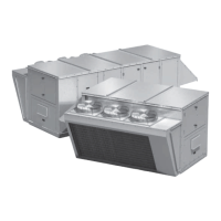
Packaged Rooftop Ventilator
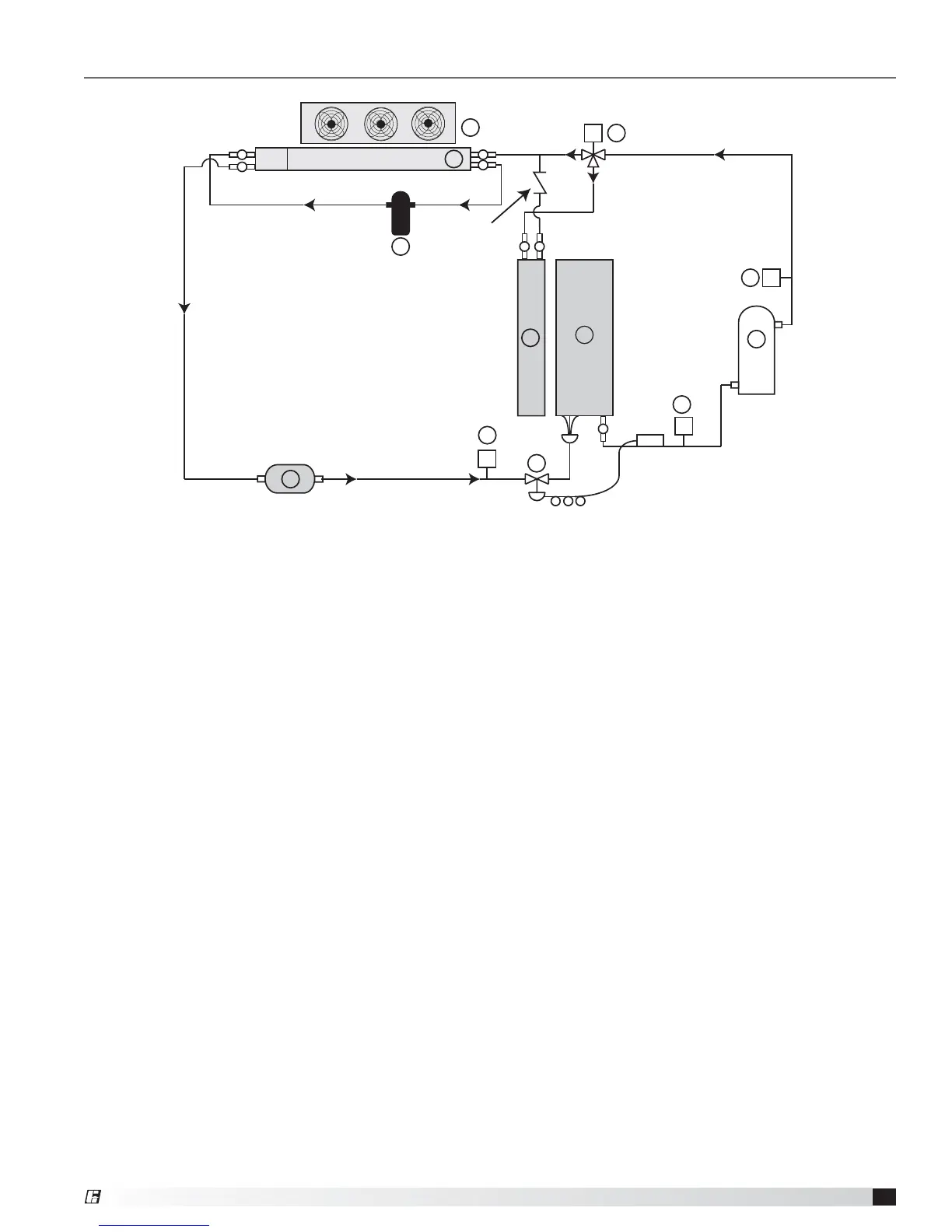
Factory-Installed Refrigeration System Components
1. Thermostatic Expansion Valve (TXV)
Each unit is equipped with a Thermal Expansion
Valve on each refrigerant circuit. The valve controls
the flow of liquid refrigerant entering the evaporator
coil by maintaining a constant, factory-set superheat
of 10°F. The valve is adjustable and is located on
the side of the evaporator coil and can be accessed
through the coil panel access door.
2. Evaporator Coil
3. Low Limit Pressure Switch
The switch is installed in the suction line and disables
the DX system when the suction pressure drops
below the set point. The switch will auto-reset when
the pressure rises above the auto-reset set point.
4. Compressors
5. Condensing Coil
6. Condenser Fans
7. High Limit Pressure Switch
The switch opens when refrigerant pressure
increases above the set point in the liquid line and it
then requires a manual reset.
8. Head Pressure Cycle Switch
9. Liquid Line Filter Drier
M
1
2
3
4
8
9
7
11
6
5
Circuit A
Check Valve
12
11
4
10. Hot Gas Bypass Valve (optional)
On units equipped with hot gas bypass, hot gas
from the compressor is injected into the liquid line
of the evaporator coil after the TXV.
Valve Adjustment - To adjust the valve, connect
a pressure gauge to the suction line and block the
entering air to the evaporator coil. The valve should
begin to open when the suction pressure drops to
approximately 115 PSIG for R-410A (the valve will
feel warm to the touch). Adjustments are made by
first removing the cap on the bottom of the valve
and then turning the adjusting stem clockwise to
increase the setting pressure (counterclockwise
to decrease). Allow several minutes between
adjustments for the system to stabilize. When
adjustment is complete, replace the cap on the
valve.
11. Reheat Valve (optional)
Units equipped with a reheat coil use a three-
way valve with actuator to control the supply
air discharge temperature of the unit during
dehumidification mode. The unit controller provides
a 0 - 10 VDC signal to control the amount of reheat
to meet the supply temperature set point.
12. Liquid Receiver (optional)
®
 Loading...