8
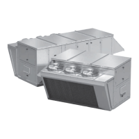
Packaged Rooftop Ventilator
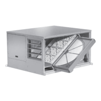
Typical Unit Installed on Rails Supplied by Others
Rail Mounting and Layout
• The units may be installed on rails provided and
installed by others. Ensure that rails are designed to
handle the weight of the unit and provide proper load
distribution on building supports.
• Make sure that rail positioning does not interfere with
the openings on the unit.
• Rails should run the width of the unit and extend
beyond the unit a minimum of 12 inches on each side.
• Set unit on rails.
Each installation is unique and as a result, alternate
entry locations may be field-located. Before using any
alternate entry location, verify the suitability of the
location and ensure the use of an alternate location
does not interfere with unit wiring, components or
functionality.
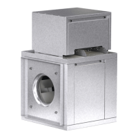
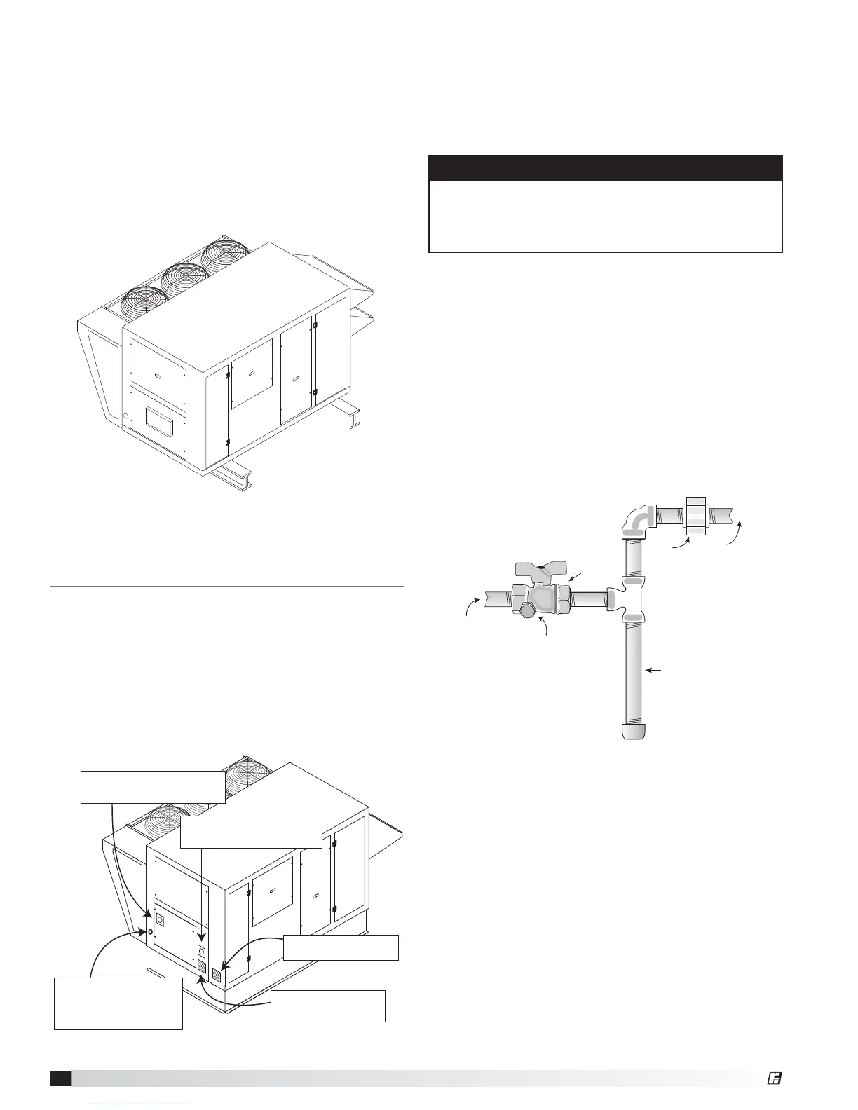
Recommended Gas and Electric Supply Entry Locations
Recommended Electrical and Gas
Supply Entry Locations
Manufacturer recommends that electrical service and
gas supply be brought into the cabinet through the
end wall, as shown below. There are three penetrations
into the cabinet that are required; one for high voltage
supply wiring, one for low voltage control wiring and one
for either gas supply or high voltage supply wiring for an
electric heater.
Alternate Supply Entry Locations
RECOMMENDED LOCATION:
Factory-provided opening for gas
supply. If electric heat is ordered,
use this location for high voltage
supply wiring for heater.
Optional Main Disconnect Switch
(Terminate high voltage supply wiring
here or at power distribution block).
RECOMMENDED LOCATION
for field-supplied high voltage
supply wiring.
RECOMMENDED LOCATION
for low voltage control wiring.
Disconnect Switch for electric heater.
Present only if electric heat is selected.
Terminate heater supply wiring here.
WARNING
Never drill holes in the roof of the unit! There is high
voltage wiring located between the inner and outer
roof panels. Damage to the wiring could cause severe
bodily harm or death.
Typical Gas Supply Piping Connection
Ground
Joint
Union
8 in. Trap
Gas to
Controls
From Gas Supply
Bleeder Valve or
1/8 in Plugged Tap
Gas Cock
Optional Gas Piping
Units with indirect gas-fired furnaces require field-
supplied and installed gas supply piping. The unit gas
connection is
3
⁄4 inch NPT. The maximum allowable gas
pressure is 14 in. wg.
Gas Connections
If this unit is equipped with an indirect gas-fired furnace,
connection to an appropriate gas supply line will be
required. For complete information on installation
procedures for the optional gas furnace, refer the
PVF/PVG Indirect Gas-Fired Heat Module Installation,
Operation, and Maintenance Manual.l.
®
 Loading...