12
Packaged Rooftop Ventilator
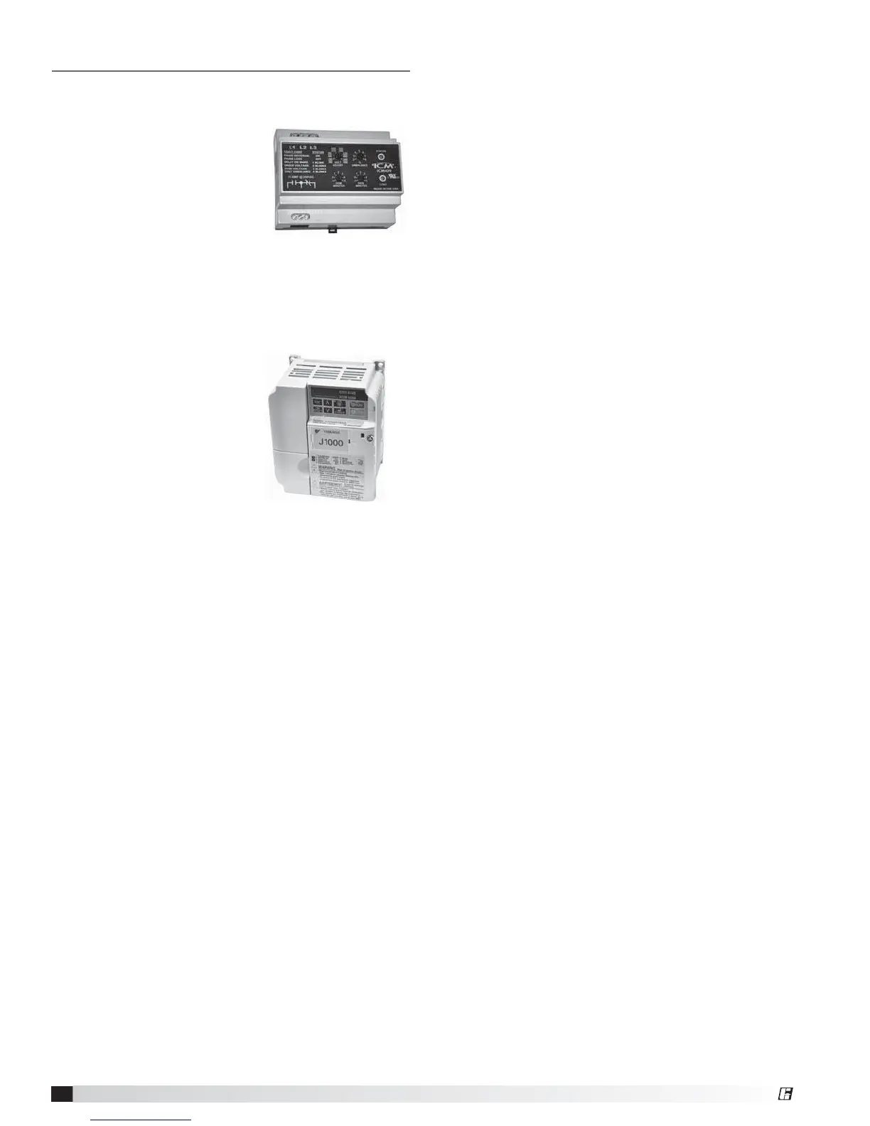
Phase Monitor
The unit control circuitry includes a phase monitor that
constantly checks for phase
reversal, phase imbalance, loss
of phase or a power brownout.
It requires 24 VAC to operate
and when it detects a fault, it
cuts off the 24 VAC that goes to
the low voltage terminal strip,
thereby shutting off all motors.
Typical Phase Monitor
Component Operation
Supply Fan VFD Sequence
Optional Room CO2 Sensor: The microprocessor
controller will modulate the supply fan based on a
comparison of the CO2 setpoint to the actual CO2
levels reported from the sensor. Mechanical high static
protection cutoffs must be installed by others to protect
the system and equipment from over-pressurization.
Optional Duct Static Pressure Sensor: The
microprocessor controller will modulate the supply fan
based on a comparison of the duct static pressure set
point to the actual duct static pressure level reported
from the sensor. Mechanical high static protection
cutoffs must be installed by others to protect the
system and equipment from over-pressurization. The
manufacturer does not assume responsibility for this.
Optional Building Static Pressure Sensor: The supply
fan is modulated based upon the signal from a building
static pressure sensor. The microprocessor controller
will modulate the supply fan based on a comparison
of the building static pressure set point to the actual
building static pressure level reported from the sensor.
Optional Single Zone VAV: The microprocessor will
use a space mounted temperature sensor to vary
heating and cooling capacity and the airflow delivered
by the fan to maintain room-air temperature at a desired
setpoint.
Optional 0-10 VDC by others to VFD The supply fan
is modulated by a 0-10 VDC provided by others in the
field.
Optional Exhaust Fan VFD Sequence
Optional Building Static Pressure Sensor: The
exhaust fan is modulated based upon the signal from
a building static pressure sensor. The microprocessor
controller will modulate the exhaust fan based upon a
comparison of the building static pressure level reported
from the sensor.
Optional Outdoor Air Damper Tracking: The
microprocessor controller will proportionally modulate
the exhaust fan based upon the outdoor air damper
position.
Optional Supply Tracking: The microprocessor
controller will proportionally modulate the exhaust fan
based upon the supply fan.
Optional 0-10 VDC by Others to VFD: The supply fan
is modulated by a 0-10 provided by by others in the
field.
Variable Frequency Drive (VFD)
If a VFD was provided and installed at the factory, it has
been pre-set to control the speed of the blower motor
for optimum performance. The motor speed needs to
be verified during test and
balance of the unit.
If the system was configured
for Constant Air Volume (CAV),
the VFD will operate in an ON
/ OFF fashion and the speed
of the motor will not change. If
the system was configured for
Variable Air Volume (VAV), the
DDC will constantly monitor
operating conditions and
provide a signal to the VFD,
changing the VFD output as needed.
The VFD may alternatively be connected to an external
signal such as provided by a BMS and be operated by a
2 - 10 VDC or a 4-20 mA input.
Typical Variable
Frequency Drive (VFD)
®
 Loading...