7
2.4
2.4.1
2.4.2
3
4 5
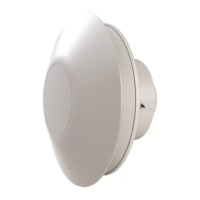
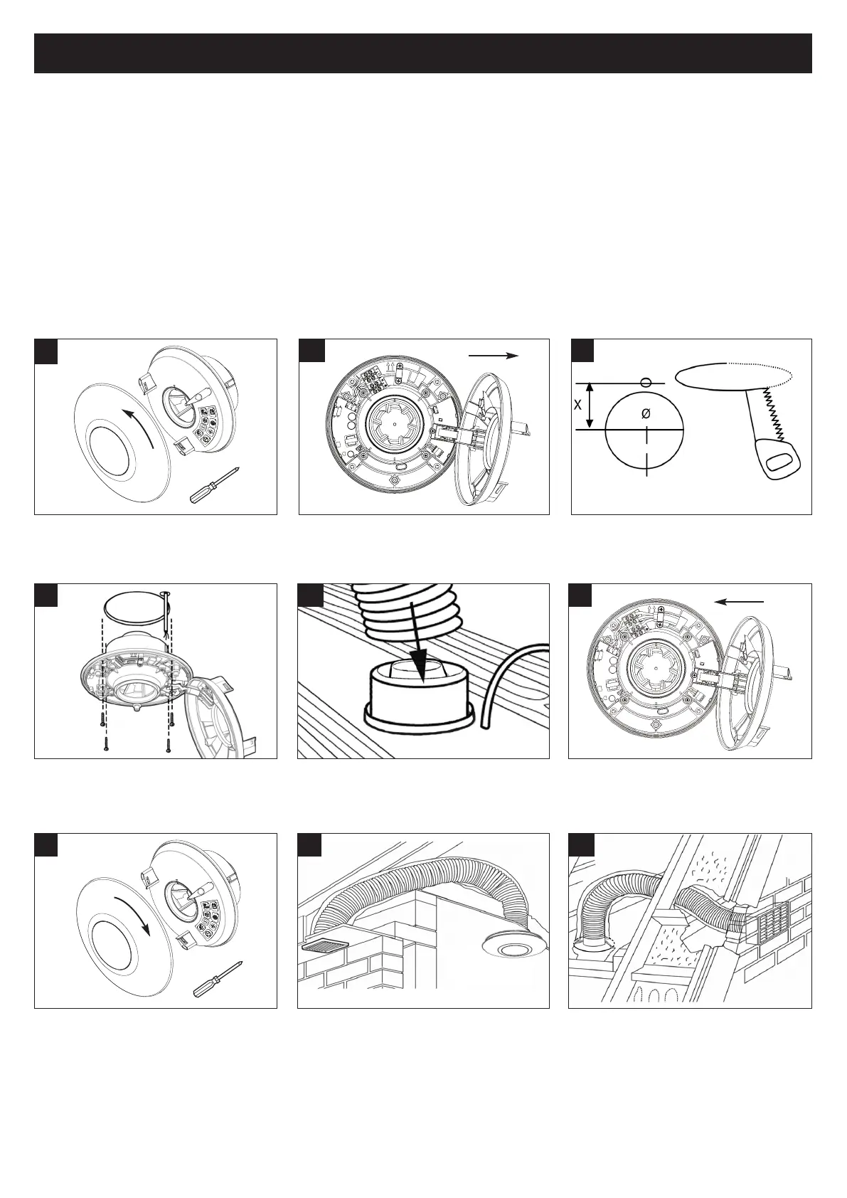
To remove outer front cover, rotate to the
left until retaining clips are released. Then
loosen the 3 fixing screws (see Note above).
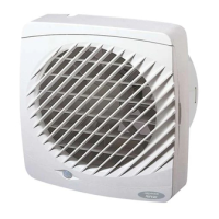
Cut an opening through the ceiling for the
fan and electrical cable.
Place flexible or rigid ducting over the
spigot of the fan. Fit ducting to spigot using
appropriate method. Refer to section 2.5.
8
Diagram depicting typical installation ducted
through roof soffit. If ducted via a roof vent
follow guidelines set out with the Domestic
Ventilation Compliance Guide.
1
9
Diagram depicting typical installation ducted
through roof to external wall.
Fully tighten the 3 fixing screws until they lock
to maintain IPX4 and avoid possible hazard. To
attach the outer front cover, rotate to the
right, utilising the guidance rail, until firmly
secured by the retaining clips.
7
6
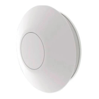
Carefully close the electronics cover,
ensuring that the outer rubber seal edges
are positioned correctly back into the fan
body.
2
Carefully open the electronics cover until
retention hinge is fully extended.
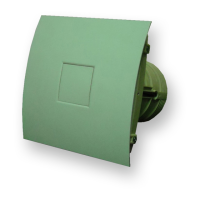
X = 65 Ø = 105mm
Ceiling Mounting
Determine the most ideal location for the unit for this installation, also
taking account of the electrical services.
Ensure there is adequate access for installation and eventual
replacement. Note: The electronics cover has been designed to retain
and hold screws, for ease, when positioning/mounting the product to a
surface.
To maintain IPX4 the unit must be securely
mounted using all four fixing holes provided
(see section 2.2). Wire fan (See wiring
details).
 Loading...