4
W450320A 08/12
Outline of Operation
The system is intended to aid the crane operator by monitoring the load and warning of an overload or
two-block condition. Crane functions are monitored by a variety of sensors.
The system compares the load suspended below the boom head to the crane capacity chart stored
within the computer’s memory.
At approach to overload, the system sends audible and visual warning signals. The system can be
configured to cause function kick-out by sending a signal to function disconnect solenoids.
System Components
• Display Unit
• Computer Unit
• Pressure Sensors
• Swing Sensor
• Reeling Drum Assembly, with Extension and Angle Sensors
• Anti-Two-Block Switches
• Cables
• Audible Alarm
• Installation/Operator Manuals
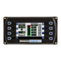
Display Unit
The display unit provides the operator with:
• Rated Capacity
• Actual Load
• Bar graph representation of Actual Load vs. Rated Capacity
• Radius of the Load
• Boom Angle
• Main Boom Length
• Working Area
• Crane Configuration
BOOM ANGLE SENSOR
The boom angle is measured by a potentiometer/pendulum assembly. It provides a voltage proportional
to boom angle. This sensor is mounted inside the cable reeling drum assembly.
EXTENSION SENSOR
The extension sensor provides a voltage proportional to the extension of the boom. The extension
sensor is mounted inside the cable reeling drum assembly.

 Loading...