Introduction
NET485 User Guide 2-3
2.4 Full Duplex-Half Duplex Jumper
The NET485 is factory set for RS485. You can change it to RS422 by changing the protocol for the port
setting. See Channel 1 Configuration on page 3-3. You can select Full or Half Duplex by changing the
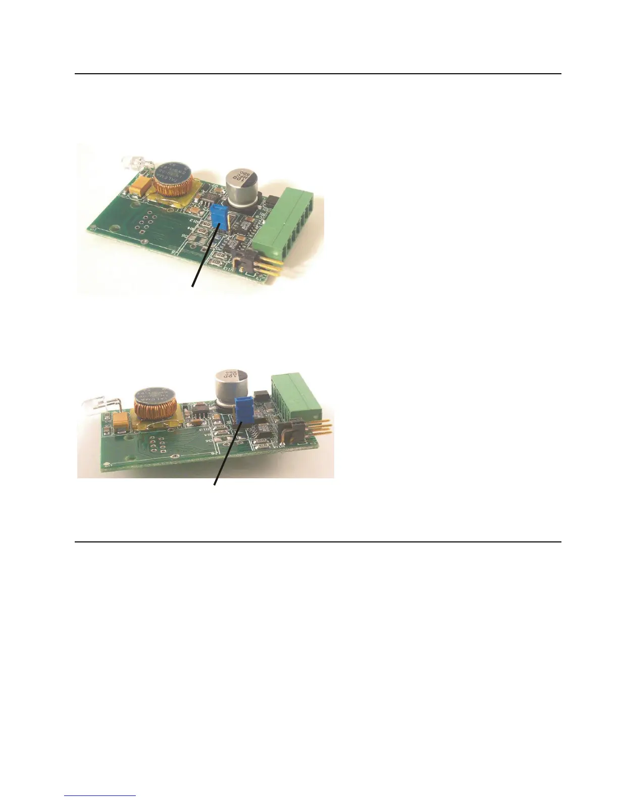
internal jumper J2. The factory default setting is Half Duplex, pins 2 and 3 are connected.
Figure 7 - J2 Setting for Half Duplex
To change the jumper J2 to Full Duplex, open the case and locate the jumper J2. Move the jumper to pins 1
and 2 as shown in the drawing.
Figure 8 - J2 Setting for Full Duplex
2.5 Power Supply
The NET485 can use a DC power source from 5VDC to 24VDC, even though the label shows 8-24VDC.
The current draw is determined by network activity and serial port communications. In general, a 2.5W
supply will handle the load.
Most modular power supplies use the same method of designating which lead is positive and which one is
negative. Generally, the lead with a white stripe, or white markings, is the positive lead. Verify the lead
markings with a meter before connecting a power source to the NET485.
Connect the positive lead to the terminal marked 8-24VDC. Connect the negative lead to the terminal
marked GND. See Figure 6 for lead identification. The power LED will come on when power is supplied.
The unit will go through a self-test and will attempt to connect to a server. The LEDs on the Ethernet
connector will indicate the connection status.