Device Installer
3-12 NET485 User Guide
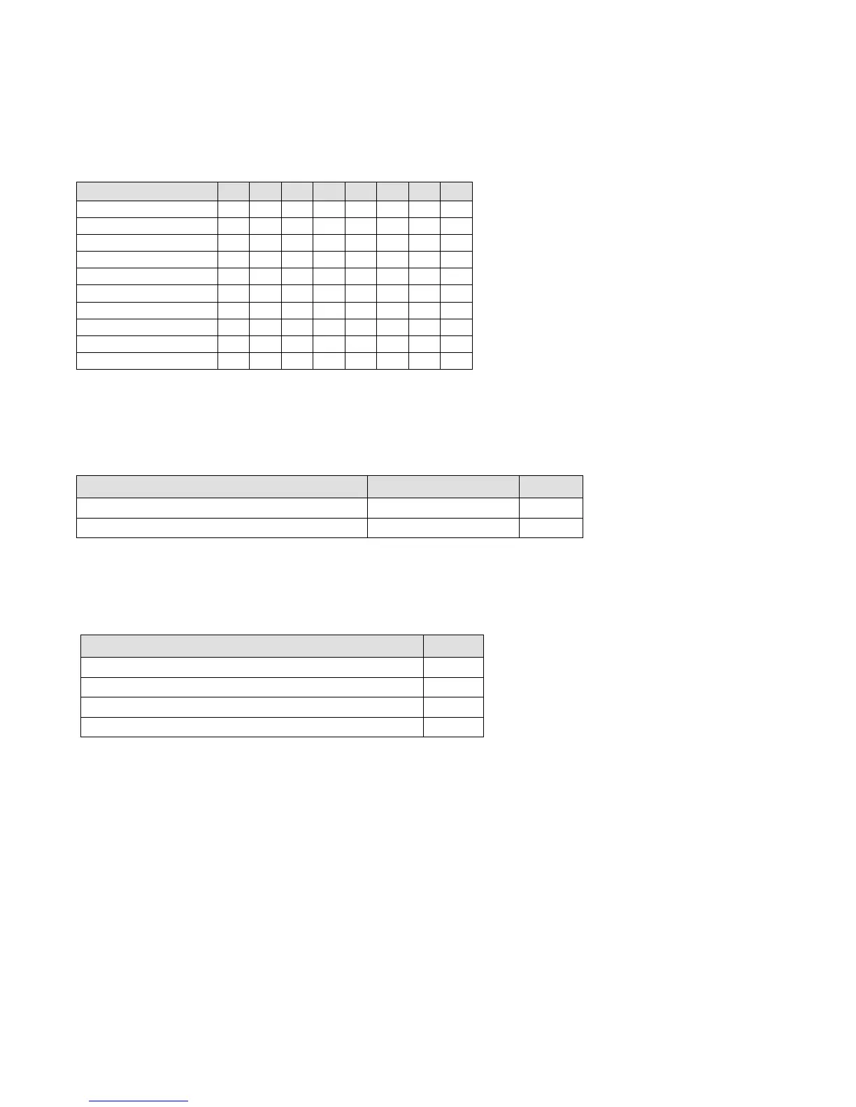
3.7.2 I/F (Interface) Mode
The Interface (I/F) Mode is a bit-coded byte that you enter in hexadecimal notation.
Table 6 - Interface Mode Options
(1) 2 stop bits are implemented by software. This might have influence on performance.
Note: RS-422/485 I/F Modes are supported on XPort-03 with firmware 6.1.0.0 and above.
The following table demonstrates how to build some common Interface Mode settings:
Table 7 - Common Interface Mode Settings
RS-232C, 8-bit, No Parity, 1 stop bit
RS-232C, 7-bit, Even Parity, 1 stop bit
3.7.3 Flow
Flow control sets the local handshaking method for stopping serial input/output.
Table 8 - Flow Control Options
Hardware handshake with RTS/CTS lines (see note)
XON/XOFF pass characters to host