6
INSTALLATION
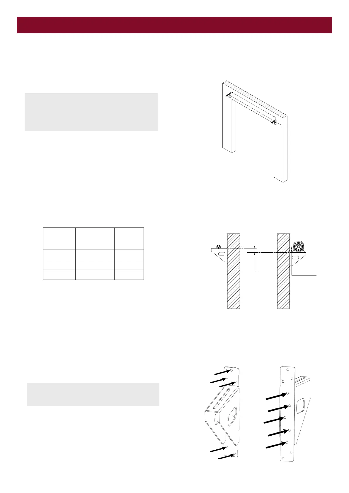
• Mark the wall with bracket positions as defined by the door
manufacturer.
NOTE: The Operator is not handed; it can be
positioned on either side of a door that best suits the
application and available side-room.
See Operator installation section for changing the
hand chain side.
• Ensure the bracket heights are correctly set to allow for the
different centre heights of the brake and the Bearing.
Bracket width
Drum centre line
X
Safety Brake
Centre Height
Safety Brake
models
Safety Brake
Centre height
"X"
GSB-547
118 mm 69 mm
GSB-1017
150 mm 93 mm
GSB-1892
180 mm 104 mm
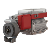
• Attach the brackets onto the wall using ALL available
mounting holes (Mounting fasteners are not provided.)
NOTE: Method of bracket installation is dependent on
the building structure and must be suitably
engineered to ensure robust and safe installation.
Safety
Brake
Models
Safety Brake
Centreline
Height
‘X’
GSB-547 118mm 69mm
GSB-1017 150mm 93mm
GSB-1892 180mm 104mm
(40mm bearing centre height: 49mm)
(50mm bearing centre height: 57mm)
(65mm bearing centre height: 76mm)
MOUNTING PLATFORM