24
C
B
A
Fig. 48
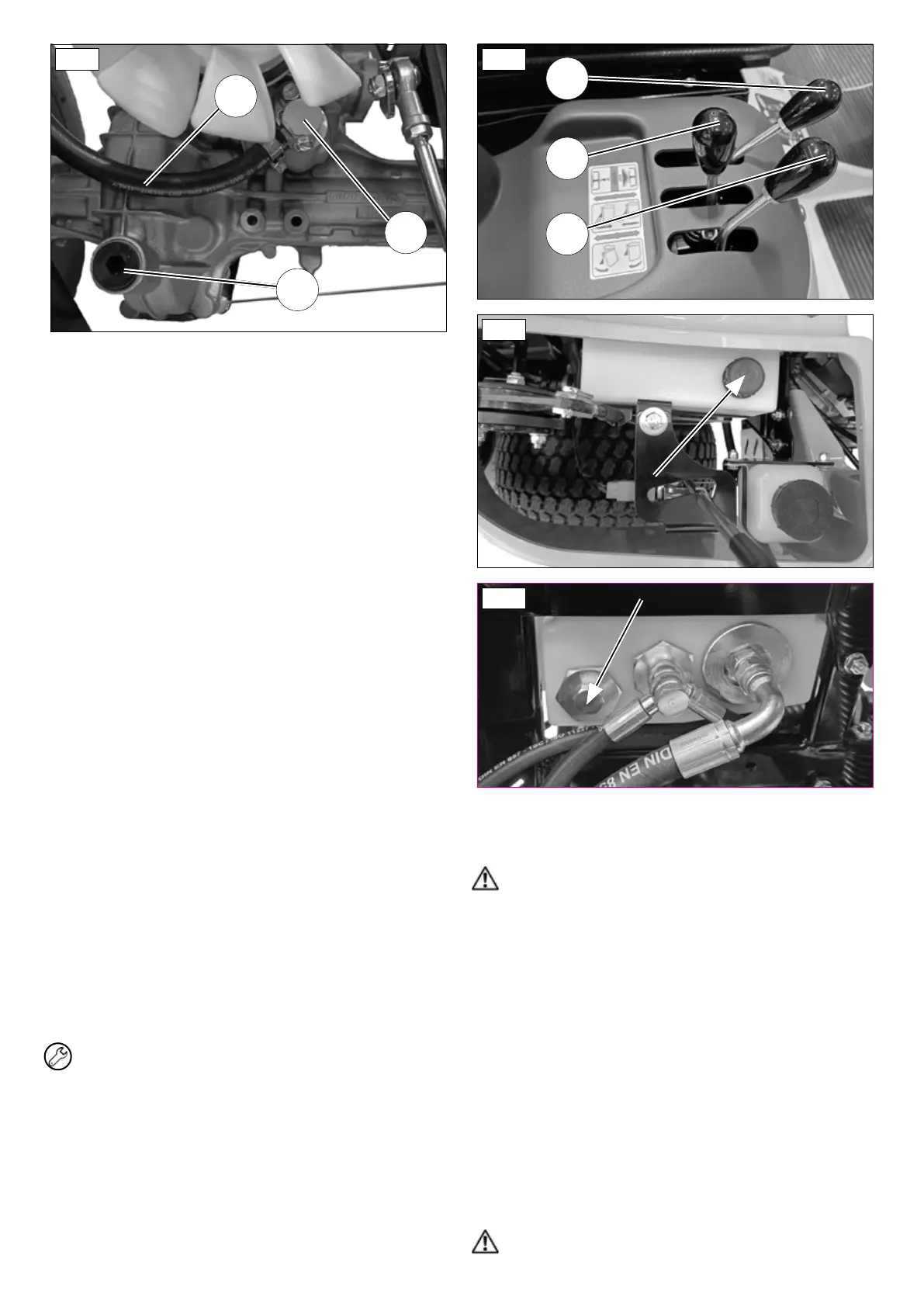
9. Bleed the hydrostatic transmission as follows:
- Place the machine safely on stands with the front wheels raised
offtheground,makesurethebypassvalveisengaged(g.46);
- Start the engine, wait a few minutes and make a few gear
changes (forwards and backwards) using the travel pedal;
- Disengage the bypass valve by pulling it towards the outside of
themachine(g.47)andcarryoutafewgearchanges(forwards
and backwards) using the travel pedal;
10. Place the machine back on the ground and check its
travel and halting; in the event of reduced performance,
loss of power or noise, repeat bleeding (point 9);
Visuallychecktheoillevelintheexpansiontank(g.43).Whenthe
engine is cold, the oil level should be approximately 1 cm from the
bottom of the expansion tank.
16.3 HYDRAULICSYSTEMMAINTENANCE
hydraulic services distributor
Thehydraulicleverdistributor(g.49)operatesatamaximumoperating
pressure of approximately 140 bar.
Lever2makesthecuttingdeckoatingorcanliftit.
Lever 3 lifts / lowers the grass catcher.
Lever 4 tips the grass catcher for unloading.
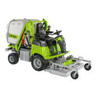
Check the level in the hydraulic oil tank periodically, when the oil is cold.
Tocheckthelevelortotopuptheoil,pullouttheoillevelcap(g.50).
Check the level by using the dipstick of the oil tank cap: the level must
be between the two notches at the end of the dipstick. Check the level
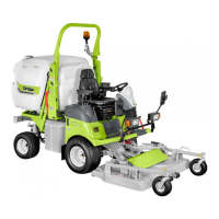
inserting the cap on and off completely each time. To remove the oil,
loosenthedrainplugonthesideofthetank(g.51).
Changethehydraulicoilthersttimeafter100hours,thenevery400
hours. It is not necessary to bleed the hydraulic system.
The oil must be changed before 100 hours if:
• The oil is dark in colour;
• The oil is off-white in colour (oil is contaminated with water);
• There are black residues (partial deterioration of the oil).
UsehydraulicoilOSO48inaquantityof3.8litresincludingllingthe
circuit.
IMPORTANT:payparticularattentiontoanycontaminationthat
couldenterthecircuitandcauseseriousdamagetothemachine.
2
3
4
Fig. 49
Fig. 50
Fig. 51
16.4 CUTTINGDECKMAINTENANCEAND
COMPLETEDISASSEMBLY
CAUTION:carryouttheoperationwiththeengineswitchedoff
andthebrakeapplied.
Proceed as follows to remove the cutting deck:
1. Remove the loading chute;
2. Lower the cutting deck bringing the distributor lever to the FLOAT
position(g.49/2)andlowerthecuttingheightcompletely;
3. Remove the guard above the cutting deck by unscrewing the two
knobs(g.52/A);
4. Removethecotterpin(g.53/B);
5. Loosen the belt by turning the lever on the tensioner anti-clockwise
(g.53/C);
6. Remove the PTO belt;
7. Unfasten the connector of the electric actuator for the height
adjustment(g.54/D);
8. Movetheframe/platequickcouplingleverbackwards(g.54/E);
9. Remove the cutting deck from the machine and place it vertically
onitssupports(g.55).
To reassemble the plate follow the procedure in reverse order.
To reassemble the cutting deck follow the procedure in reverse order.
CAUTION:whenrettingtheplate,checkthattheloadingchute