Model G0869/G0870 (Mfd. Since 01/19)
-19 -
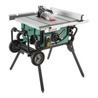
Site Considerations
Figure 10. Minimum working clearances.
50½"
(G0870)
37½"
44½"
(G0869)
Children and visitors may be
seriously injured if unsuper-
vised around this machine.
Lock entrances to the shop
or disable start switch or
power connection to prevent
unsupervised use.
Workbench Load
Refer to the Machine Data Sheet for the weight
and footprint specifications of your machine.
Some workbenches may require additional rein-
forcement to support the weight of the machine
and workpiece materials.
Consider anticipated workpiece sizes and addi-
tional space needed for auxiliary stands, work
tables, or other machinery when establishing a
location for this machine in the shop. Below is
the minimum amount of space needed for the
machine.
Placement Location
Assembly
Assembly of Model G0869/G0870 consists of
installing the fence, table extension, and blade
guard/spreader with anti-kickback pawls.
Additionally, the roller stand that comes with
Model G0870 must be assembled and the saw
mounted to it.
1. Place fence on rails with fence mounting
holes positioned over (2) pre-installed mount-
ing screws, then tighten (2) pre-installed
fence lock knobs to secure (see Figure 11).
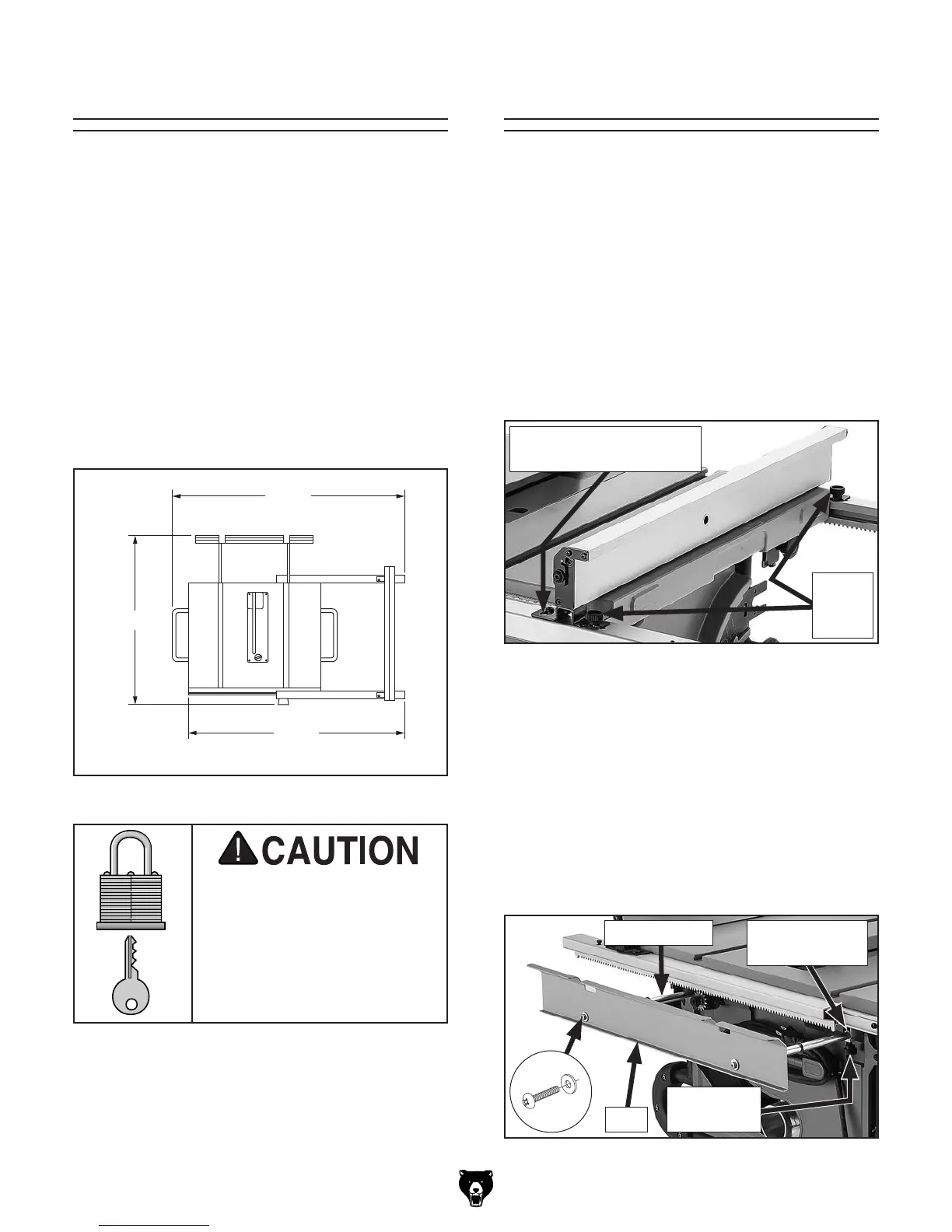
Installing Fence & Table Extension
Figure 11. Fence installed.
Fence
Lock
Knobs
Fence Mounting Hole/
Mounting Screw (1 of 2)
2. Attach table extension rest to (2) table exten-
sion shafts using (2) 6mm flat washers and
(2) M6-1 x 10 Phillips head screws (see
Figure 12).
3. Insert table extension shafts into mounting
holes on rear of machine (see Figure 12).
4. Thread (2) table extension lock knobs into
locations shown in Figure 12.
Figure 12. Table extension partially installed.
Mounting Hole
(1 of 2)
Rest
x 2
Shaft (1 of 2)
Lock Knob
(1 of 2)
 Loading...