24 25
5.7.3. Connecting the PV array
5.7.3.1. Conditions for DC connection
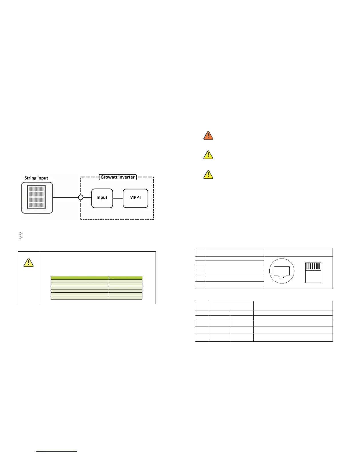
The inverter has 1 independent string input.
The diagram drawing of DC side is shown as below, notice that the connectors are
in paired (male and female connectors). The connectors for PV arrays and
inverters are H4 connectors;
Requirements for the PV modules of the connected strings:
Same type
Same quantity of PV modules connected in series
CAUTION
If the inverter is not equipped with a DC switch but this is mandatory
in the country of installation, install an external DC switch.
The following limit values at the DC input of the inverter must not be
exceeded:
5.7.3.2. Connecting the PV array (DC)
DANGER
Danger to life due to lethal voltages!
Before connecting the PV array, ensure that the DC switch and AC breaker
are disconnect from the inverter.Never connect or disconnect the DC
connectors under load.
WARNING
Improper operation during the wiring process can cause fatal injury to
operator or unrecoverable damage to the inverter. Only qualified personnel
can perform the wiring work.
Risk of damage to the inverter.
If the voltage of the PV modules exceeds the maximum input voltage of the
inverter, it can be destroyed by the overvoltage. This will void all warranty
claims.Do not connect strings to the inverter that have an open-circuit
voltage greater than the maximum input voltage of the inverter.
WARNING
Check the connection cables of the PV modules for correct polarity and make sure that the
maximum input voltage of the inverter is not exceeded. At an ambient temperature over 10
℃, the open circuit voltage of the PV modules should not exceed 90% of the maximum input
voltage of the inverter. Otherwise, the maximum inverter input voltage may be exceeded at
low ambient temperatures.
5.7.4 Inverter demand response modes (DRMs,only for Australia)
This series inverter has the function of demand response modes,moreover, We
use RJ45 socket as inverter DRED connection.
5.7.4.1 RJ45 socket pin assignment
5.7.4.2 Method of asserting demand response modes
MODE
Rj45 socket
Asserted by shorting pins
Requirement
DRM0
DRM5
DRM6
DRM7
DRM8
5
6
Operate the disconnection device
Do not generate power
Do not generate at more than 50% of rated power
Do not generate at more than 75% of rated power
AND Sink reactive power if capabie
Increase power generation (subject to constraints
from other active DRMs)
1
5
2
5
3
5
4
5
Assignment for inverterscapable of
both charging and discharging
PIN
1
DRM5
2
DRM6
3
DRM7
4
DRM8
5
RefGen
6
COM/DRM0
7
/
8
/
1
→
8
Pin Assignments Front View
RJ45 Socket
12345678
RJ45 Plug