32
33
Test fail condition:
Condition
Reason Suggestion
Test Stop Communication lose or inverter
occur other fault when testing
Check the communication or
check the inverter state
Test fail The trip value of the test result is
not in the limit of the spec
Check the grid state, make sure
the grid is stable, and retest
6.2.3. GFCI function
GFCI is short for Ground-Fault Circuit Interrupter which is used for preventing
from being electric shock. The inverter is equipped with integrated RCD (Residual
Current Protective Device) and RCM (Residual Current Operated Monitor). The
current sensor will detect the volume of the leakage current and compare it with
the pre-set value. If the leakage current is above the permitted range, the RCD will
disconnect the inverter from the AC load.
6.2.4. PV isolation detection
The ISO function a protection mechanism. The inverter measures the resistances
between both the positive pole and negative pole of PV panel and earth.
Either of the measured value is lower than the limit, the PV inverter will not
connect to grid, the output relay will stay open, and show 'PV isolation low'. The
limited value is determined by the standards. The firmware setting of our PV
inverters is 500Kohm.
The simplified principle of the isolation resistance measurement is described as
below:
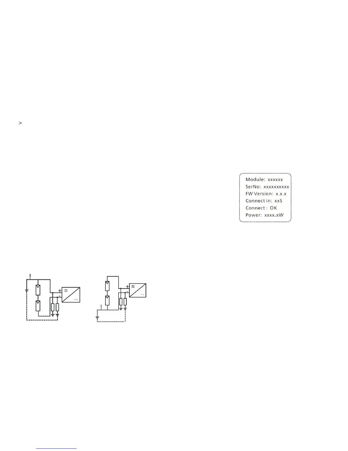
6.3. LCD display
In the lower center of inverter there is the LCD display. We can check inverter
running status, etc. on the LCD screen. Items displayed can be changed by knock;
you can also change some inverter parameters by knock.
6.3.1. General LCD display
Starting-up display sequence , once the PV power is sufficient , inverter displays
information as shown in the flow chart as follow:
Power on LCD display
6.3.1.1. The first line of LCD
Standby When the input voltage falls to 70V,inverter
will display standby.The inverter will shut
down when input voltage is lower than 60V.
Connect in xxS
System checking
Reconnect in xxS
System checking
Power: xxxx.xW
Inverter output power in normal mode.
DISPLAY CONTENT
REMARK
STATUS
Waiting
When the input voltage is between 70V and
80V during start up, inverter will display
‘waiting’
Waiting
Connect OK
Connecting to the gridNormal
Error: xxx
System fault
Fault
Auto Testing
Protecting function
Auto Test
Programming Programming
Firmware update