Remark:
CT wire (5m in length) specification: RJ45, standard LAN line (one end with 8P
modu-
lar plug, the other connected with transformer). But if the length is not enough,
customer can add cable, so the length can be increased to 15m max, the operation
Chart 5.31
Chart 5.33
Chart 5.34
Chart 5.32
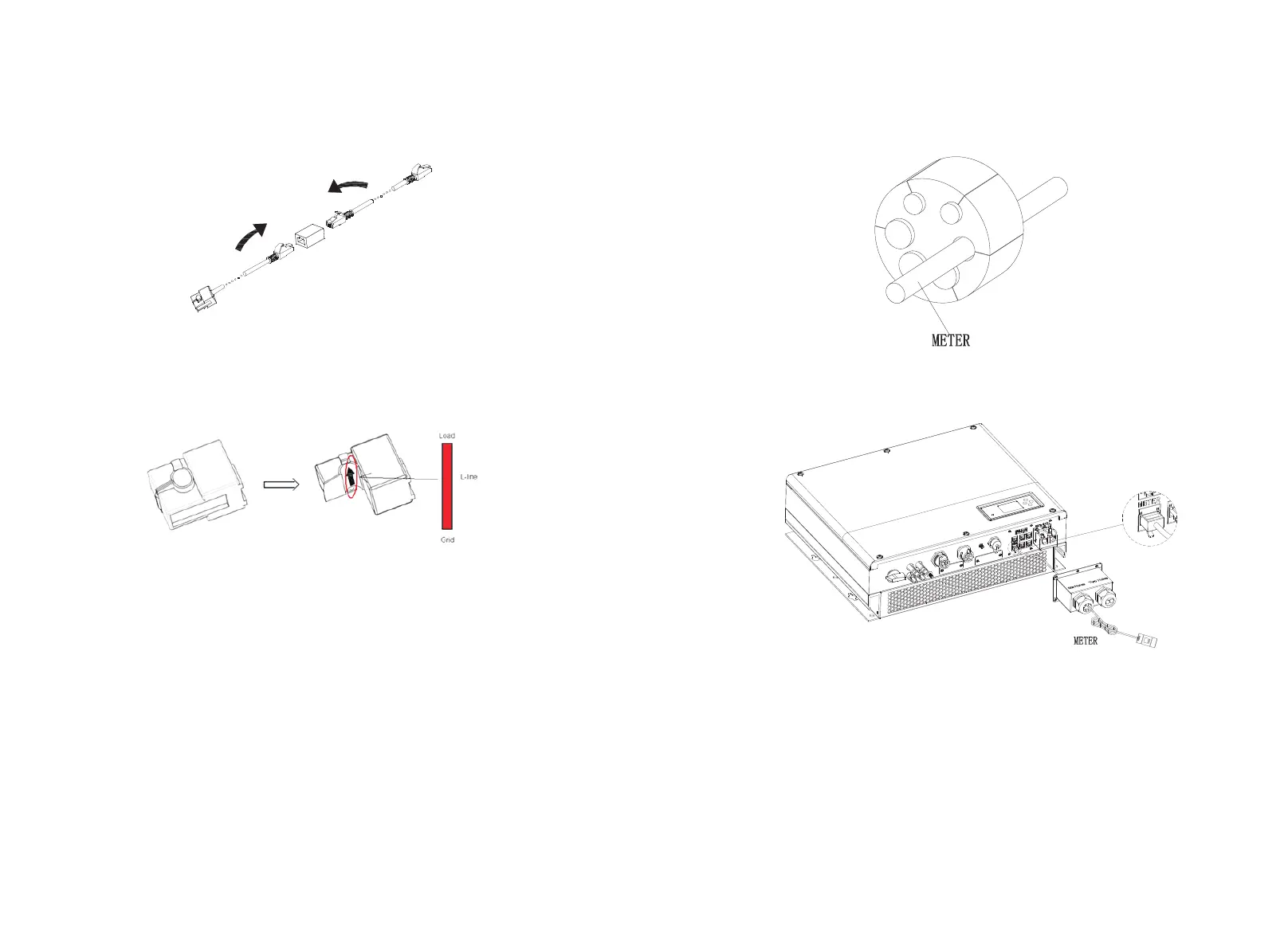
During the actual operation, please pay attention to the installation of current
transformer as the diagram shows below:
As illustrated above, open the current transformer and you can see an arrow
labeled on it indicating the direction of current. Put the live wire among the under-
detection wires onto the current transformer. After latching the current
transformer, the installation has been finished
Notice:
The direction (from K to L) of the arrow on the current transformer is
corresponding to the direction of the current in live wire from Grid to Load. Sensor
needs to be placed in the power distribution cabinet.
5.5.5 Connection of meter terminal
When customer needs to use meter to monitor the energy flow, the meter terminal
connection steps are as follows:
1.Reference 5.2, make LAN cables with RJ45 terminal.
2.Thread the swivel nut over the LAN cable.
3.Press the cable support sleeve out of the cable gland.
4.Remove the filler plug from the cable support sleeve.
5.Route the LAN cable through an opening in the cable support sleeve.
6.Thread the LAN cable through the cable gland.
7.Insert the RJ45 plug of the network cable into the “METER” pin connector on the
inverter until it snaps into place.
8.If no other cables need to be installed, lock the waterproof cover to the inverter
with screws.
9.Screw the swivel nut onto the waterproof cover.
Note:
1.Meter and CT can't be installed at same time, please set the sensor model
when selecting CT or electricity meter, please refer to section 6.3.3 for details.
2.Meter must be provided by Growatt. If not, maybe meter can't communicate
with SPH inverter.
3.The more detail describe of meter installation, please turn to meter user
27
28

 Loading...