31
32
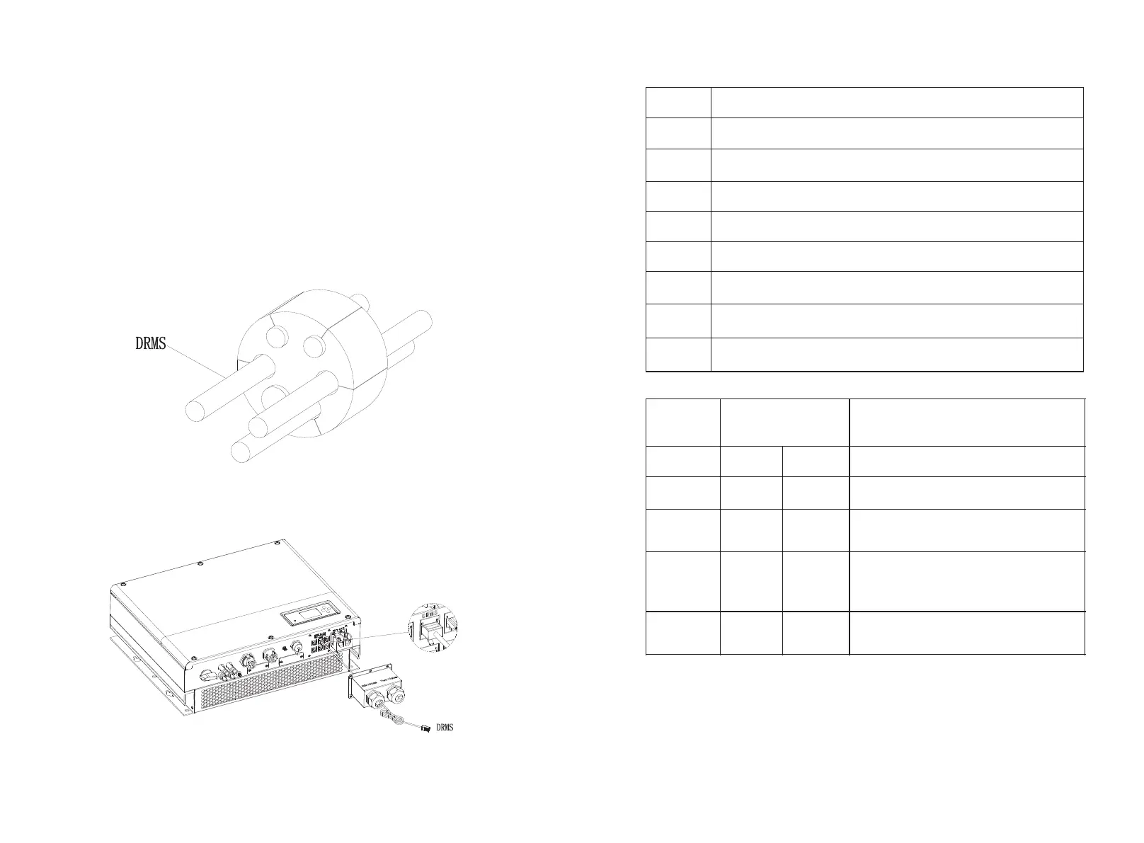
5.5.8 Connection of DRMS terminal
The DRMS terminals need to be connected ,the connection way appears as
follows:
1.Unscrew the swivel nut from the cable gland.
2.Thread the swivel nut over the “DRMS” cable.
3.Press the cable support sleeve out of the cable gland.
4.Remove the filler plug from the cable support sleeve.
5.Route the “DRMS” cable through an opening in the cable support sleeve.
6.Thread the “DRMS” cable through the cable gland.
7.Insert the RJ45 plug of the network cable into the “DRMS” pin connector on the
inverter until it snaps into place.
8.If no other cables need to be installed, lock the waterproof cover to the inverter
with screws.
9.Screw the swivel nut onto the waterproof cover.
Chart 5.39
Chart 5.40
RJ45 terminal pin assignment
RJ 45 socket
asserted by shorting
Operate the disconnection device
Do not generate at more than 50% of
rated power
Do not generate at more than 75% of
rated power and sink reactive power if
capable
Increase power generation (subject to
constraints from other active DRMs)
Method of asserting demand response modes
Assignment for inverter scapable of both charging and
Note:
If the cable such as “NTC” (lead-acid battery temperature sensor) cable is not
used, please do not remove the filler plug from the cable support sleeve.
Note
For UK This equipment is equipped with RJ45 terminal for logic interface that
being received the signal from the DNO, the connection should be installed per
installation manual, and the signal should be a simple binary output that
captured by RJ45 terminal( PIN 5 and 1 for detecting the signal). Once the
signal actived, the inverter will reduce its active power to zero within 5s.
:
:

 Loading...