EasyManuals Logo

Growatt SPH Series User Manual

Growatt SPH Series
36 pages
To Next Page IconTo Next Page
To Previous Page IconTo Previous Page
Page #25 background imageLoading...
Page #25 background image
41 42
6.4 Display and button
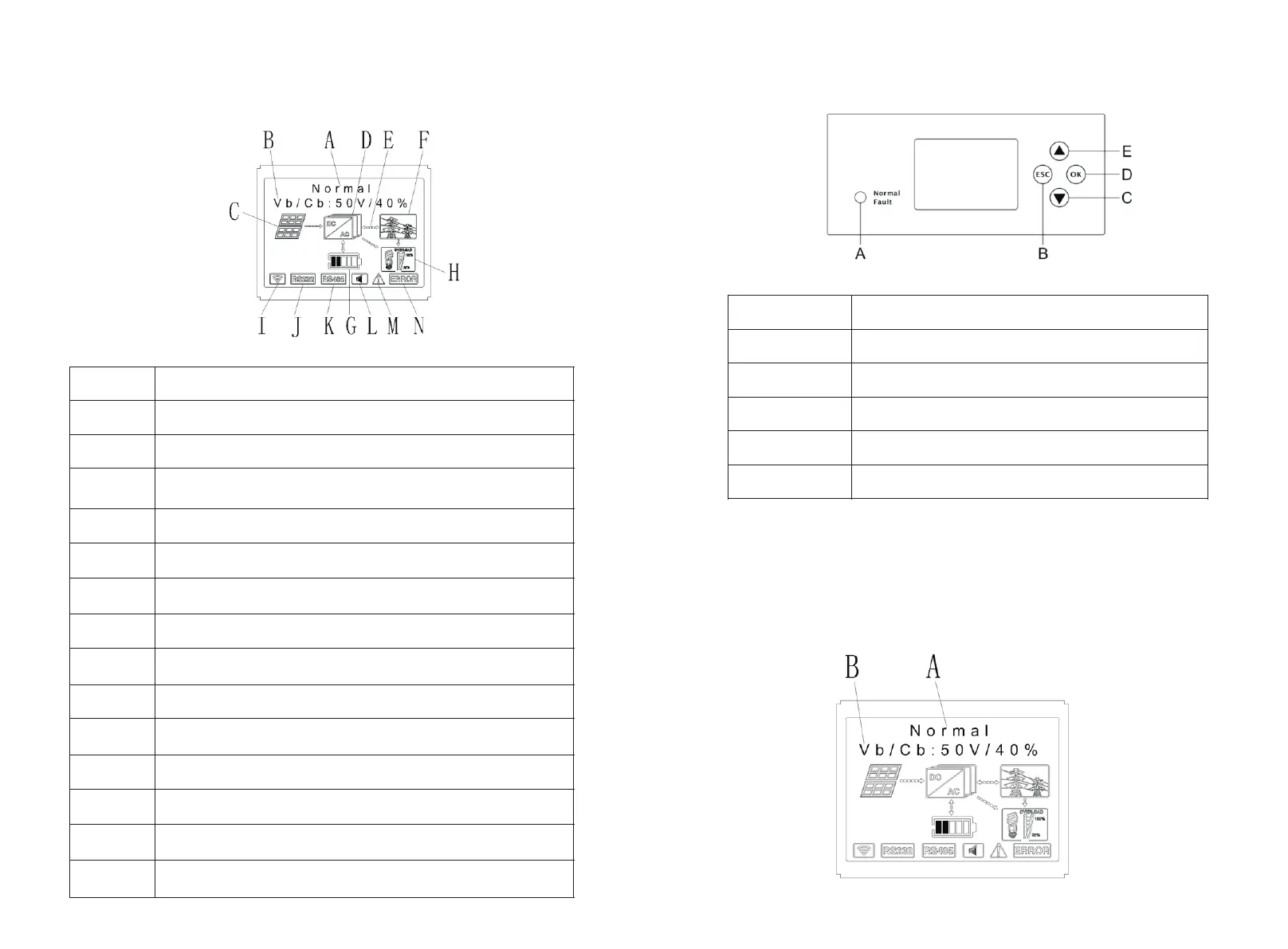
6.4.1 LCD display area
Chart 6.2
Location
Description
A
State
B
Information
C
D
SPH inverter
E
Power flow line
F
Grid
G
H
Local load
I
Wireless communication
J
RS 232
K
RS 485
L
Buzzer(Reserved)
M
Warning
N
Fault
PV input (If you connect two tracks, it will show two.
Otherwise show one)
Battery (Show the SOC in five grid, Every grid represents 20%)
6.4.2 LED and button instruction
Chart 6.3
Location
Description
Status
ESC- button(cancel control)
Down-button
Enter-button
UP-button
A
B
C
D
E
NoticeLED showing status of SPH, it has two color, one is green and another is red.
Please turn to 3.1 and read the detail of LED.
6.4.3 LCD display column
LCD display column is used to show the current state, basic information and fault
information. Also include language setting, program charging/discharging priority and
system time. On default condition will take turns to display the information.
Chart 6.4

Other manuals for Growatt SPH Series

Questions and Answers:

Question and Answer IconNeed help?

Do you have a question about the Growatt SPH Series and is the answer not in the manual?

Growatt SPH Series Specifications

General IconGeneral
TypeHybrid Inverter
Max. Input Voltage600V
Number of MPPTs2
Protection RatingIP65
Output Power Range3kW - 10kW
Rated AC Output Power3-10 kW
Communication InterfacesRS485, USB, Wi-Fi
Output Voltage230 V
Frequency50/60 Hz
Operating Temperature-25°C to 60°C
Cooling MethodNatural Convection

Related product manuals