3
PUMP CONSTITUENTS
PUMP CONSTRUCTION
Drive Section
Pumping Section
1
5
2
4
3
The pump is made up of two sections as given below :-
• Drive section :- It consists of an Air Motor Assembly driven
by compressed air. The piston diameter of the air motor is
2.5” / 63 mm. The motor consists of an air cylinder with
piston and one reciprocal valve with a nylon slider. The valve
directs the compressed air alternately to the top or bottom
of the piston, thus producing a reciprocating motion of the
piston rod.
• Pumping Section :- It consists of a pump in which a piston
lifts the grease through Non Return Valves by reciprocating
inside the pump cylinder. The grease is discharged with
pressure (from the outlet located at bottom of Air Motor) into
the delivery hose.
NOTE
AIR MOTOR of these pumps starts automatically when the
Grease Control Valve is opened. When the valve is closed, Air
Motor builds up a back-pressure and stops operating the pumping
section.
PRESSURE RATIO of the pump states the ratio of the output
grease pressure to the incoming air pressure. When the pressure
ratio is 50:1, we achieve an output grease pressure up to 7500 PSI
(500 BAR) when the incoming air pressure is 150 PSI (10 BAR ).
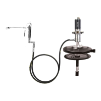
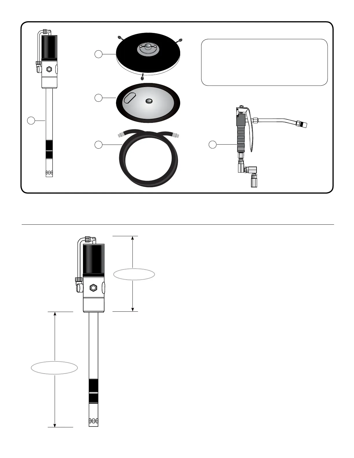
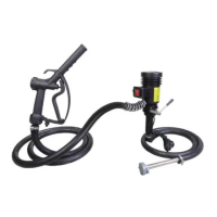
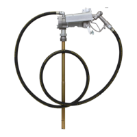
1. Grease Pump Assembly
2. Drum Cover with Thumb Screws
3. Rubber Lined Follower Plate
4. High pressure Rubber Hose
5. Professional Grease Control Valve with Z Swivel
Fig. 2
Fig. 3