8
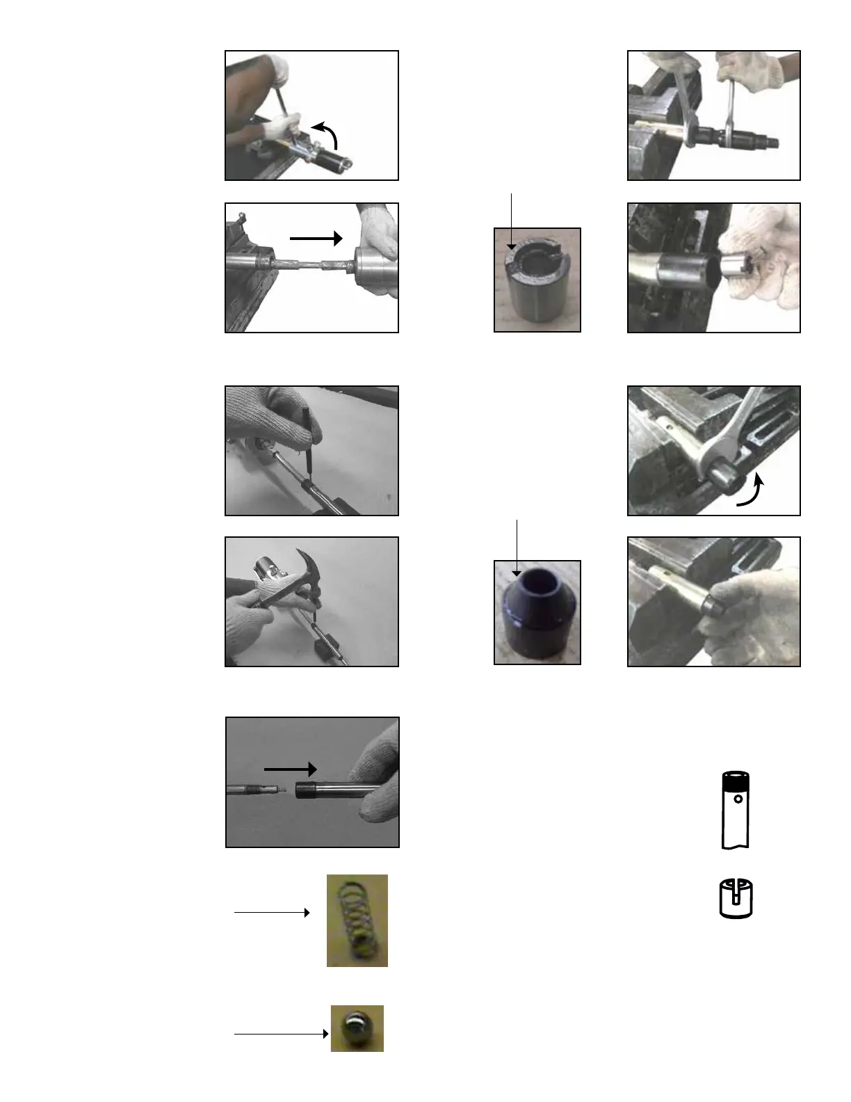
5. Tighten a 1/2” male
threaded pipe into the
outlet port & unscrew
Air Motor Assembly
anticlockwise. Carefully
remove Air Motor from
Barrel (63).
6. Support Pump Cylinder
(51) on a V block &
insert a pin punch
vertically into the hole
of Pump Cylinder (51).
Tap lightly with a hammer
to drive out lower Slotted
Spring Pin (44) taking
care not to bend the
Extension Rod (46).
7. Unscrew Pump Cylinder
(51) & remove upper
Steel Ball (47) & Non
Return Spring (48).
8. Hold Filter Tube (57) in
vice. Using two wrenches
(size 28 mm), hold Bottom
Coupler (54) & unscrew
Top Coupler (52). Remove
Slide Bush (53).
9. Unscrew Bottom Coupler
(54) with wrench (size 28
mm) & remove Guide Bush
(56).
• Pump Cylinder (51) has a pin-hole
end that must face upwards;
towards Extension Rod (46).
• Slide Bush (53) has a slotted end
that must always face upwards;
towards Top Coupler (52).
Non return
Spring
Steel Ball
10. Replace the Repair Kit (KIT/BTM/RPG) as mentioned in Table
5 - Page 17, by following the steps 1-9 in reverse order taking
care of the points below:
• Replace Part No. 51, 52, 53 & 55 TOGETHER as a set
even if there is a need to replace only one of these
parts. Apply minor grease on all the moving parts
before assembly. Also, ensure movement of part 51,
52 & part 53, 55 is smooth.
Guide Bush
Slide Bush