English (GB)
5
4. Specifications
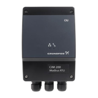
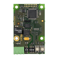
4.1 CIM module
4.2 CIM 200 Modbus RTU
The table below provides an overview of the specifications for the
Grundfos CIM 200. For further details, please refer to the specific
sections of this functional profile.
* Can only be set via software.
General data Description Comments
Ambient humidity 30 % to 95 % Relative, non-condensing.
Operating temperature -20 °C to +45 °C
Storage temperature -25 °C to +70 °C
Battery, lithium-ion
The battery will only be charged if the
battery temperature is within 0 °C to +45 °C.
CIM 250 only.
GENIbus visual diagnostics LED2
Will be in one of these states:
Off, constantly green, flashing red, constantly red.
See section 5.5 Status LEDs.
Modbus RTU specifications Description Comments
Modbus connector Screw-type terminal
3 pins.
See section 5. Modbus RTU, CIM 200 setup.
Modbus connection type RS-485, 2-wire + common
Conductors: D0, D1 and common.
See section 5. Modbus RTU, CIM 200 setup.
Maximum cable length 1200 m Equals 4000 ft.
Slave address 1-247
Set via rotary switches SW6 and SW7.
See section 5.3 Modbus address selection.
Line termination On or off
Set via DIP switches SW1 and SW2.
See section 5.4 Termination resistor.
Recommended cable cross-section 0.20 - 0.25 mm
2
AWG24 or AWG23
Supported transmission speeds
1200*, 2400*, 4800*, 9600, 19200,
38400 bits/s
Set via DIP switches SW4 and SW5.
See section 5.1 Setting the Modbus transmission
speed.
Start bit 1 Fixed value.
Data bits 8 Fixed value.
Stop bits 1 or 2
Set via DIP switch SW3.
See section 5.2 Setting the parity.
Parity bit Even parity, odd parity* or no parity
Set via DIP switch SW3.
See section 5.2 Setting the parity.
Modbus visual diagnostics LED1
Off, flashing green, flashing red, constantly red.
See section 5.5 Status LEDs.
Maximum number of Modbus devices 32
Using repeaters, this number can be increased.
Legal address range is 1-247.
Maximum Modbus telegram size 256 bytes
Total length. Node address and CRC included.
See section 12. Modbus RTU telegram examples.

 Loading...
