5.4 CM 10, 15, 25, cast iron
5.4.1 Dismantling
1. Remove staybolts (pos. 26).
2. Remove inlet part (pos. 6) and gasket (pos. 139b).
3. Hold clamp (pos. 64c), and remove nut (pos. 67).
4. Remove lock washers (pos. 66) and clamp (pos. 64c).
5. Remove impeller (pos. 49) and spacing pipe (pos. 64).
6. Remove chamber (pos. 4).
7. Continue the dismantling until shaft seal (pos. 105).
8. Remove shaft seal (pos. 105).
TM044327
Exploded view of shaft seal
9. Loosen and remove screws (pos. 2b) and discharge part (pos.
2).
Dismantling of MG 71 and MG 80, see the section on dis-
mantling.
Dismantling of MG 90, MG 100, MG 112 and MG 132, see
the section on dismantling.
It is advisable always to replace wear rings (pos. 45) and
wear ring retainers (pos. 65).
See the section on checking and replacing impellers and
chambers.
Related information
5.6.1 Dismantling
5.7.1 Dismantling
5.8 Checking and replacing impellers and chambers
5.4.2
Assembly
Assembly of MG 71 and MG 80, see the section on as-
sembly.
Assembly of MG 90, MG 100, MG 112 and MG 132, see
the section on assembly.
1. Fit discharge part (pos. 2).
2. Fit and tighten screws (pos. 2b). See the section on tightening
torques and lubricants.
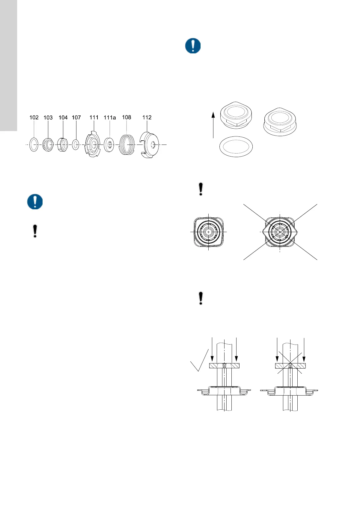
3. Fit O-ring (pos. 102) on the stationary shaft seal part. See the
section on tightening torques and lubricants.
TM044322
Fitting the O-ring on the stationary shaft seal part
4. Press the stationary shaft seal part home.
Do not touch the seal face.
TM045051
Fitting the stationary shaft seal part (only SiC/SiC)
5. Fit the rotating shaft seal part (pos. 104) so that the seal face
touches the stationary part.
Do not touch the seal face.
6. Fit O-ring (pos. 107) into the rotating shaft seal part (pos.
104). See the section on tightening torques and lubricants.
7. Fit retainer (pos. 111) and stop ring (pos. 111a).
TM044325
Fitting the stop ring
14
English (GB)
 Loading...


