5.6 MG 71 and MG 80 motors
5.6.1 Dismantling
1. Remove screws (pos. 152).
2. Remove fan cover (pos. 151).
3. Remove fan (pos. 156) and seal ring (pos. 159a).
4. Remove screws (pos. 181).
5. Remove motor flange (pos. 156b) and gasket (pos. 157a).
6. Remove diverting disc (pos. 79), O-ring (pos. 158a) and bearing
cover plate (pos. 155).
7. Pull shaft (pos. 51) out of stator housing (pos. 150).
8. Pull bearing (pos. 153) off shaft (pos. 51).
9. Remove O-ring (pos. 159) and spring (pos. 158).
10. Pull bearing (pos. 154) off shaft (pos. 51).
5.6.2 Assembly
1. Push bearing (pos. 154) onto shaft (pos. 51).
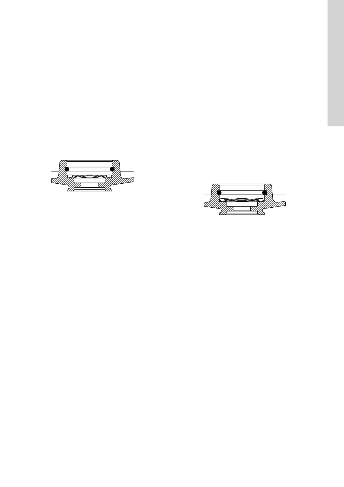
2. Fit spring (pos. 158) and O-ring (pos. 159).
TM044441
Correct fitting of spring and O-ring
3. Push bearing (pos. 153) onto shaft (pos. 51).
4. Fit shaft (pos. 51) into stator housing (pos. 150).
5. Fit bearing cover plate (pos. 155), O-ring (pos. 158a) and
diverting disc (pos. 79). Lubricate the surface of the cover plate
(pos. 155) turning against the bearing. Lubricate the O-ring (pos.
158a). For correct lubricant, see the section on tightening
torques and lubricants.
6. Fit gasket (pos. 157a) and motor flange (pos. 156b).
7. Fit and cross-tighten screws (pos. 181). See the section on
tightening torques and lubricants.
8. Fit and lubricate the seal ring (pos. 159a). For correct
lubricant, see the section on tightening torques and lubricants.
9. Fit the fan (pos. 156).
10. Fit fan cover (pos. 151).
11. Fit and tighten screws (pos. 152).
Related information
3. Tightening torques and lubricants
5.7
MG 90, MG 100, MG 112 and MG 132 motors
5.7.1 Dismantling
1. Only cast iron pumps: Remove screws (pos. 2b).
2. Only cast iron pumps: Remove discharge part (pos. 2).
3. Remove screws (pos. 152).
4. Remove fan cover (pos. 151).
5. Remove fan (pos. 156) and seal ring (pos. 159a).
6. Remove staybolts (pos. 181).
7. Remove motor flange (pos. 156b), gasket (pos. 157a) and
bearing cover (pos. 156a).
8. Remove diverting disc (pos. 79), O-ring (pos. 158a) and bearing
cover plate (pos. 155).
9. Pull shaft (pos. 51) out of stator housing (pos. 150).
10. Pull bearing (pos. 153) off shaft (pos. 51).
11. Remove O-ring (pos. 159) and spring (pos. 158).
12. Pull bearing (pos. 154) off shaft (pos. 51).
5.7.2 Assembly
1. Push bearing (pos. 154) onto shaft (pos. 51).
2. Fit spring (pos. 158) and O-ring (pos. 159).
TM044441
Correct fitting of spring and O-ring
3. Push bearing (pos. 153) onto shaft (pos. 51).
4. Fit shaft (pos. 51) into stator housing (pos. 150).
5. Fit bearing cover plate (pos. 155), O-ring (pos. 158a) and
diverting disc (pos. 79). Lubricate the surface of the cover plate
(pos. 155) turning against the bearing. Lubricate the O-ring (pos.
158a). For correct lubricant, see the section on tightening
torques and lubricants.
6. Fit bearing cover (pos. 156a), gasket (pos. 157a) and motor
flange (pos. 156b).
7. Fit and cross-tighten staybolts (pos. 181). See the section on
tightening torques and lubricants.
8. Fit and lubricate the seal ring (pos. 159a). For correct see the
section on tightening torques and lubricants.
9. Fit the fan (pos. 156).
10. Fit fan cover (pos. 151).
11. Fit and tighten screws (pos. 152). See the section on tightening
torques and lubricants.
12. Only cast iron pumps: Fit discharge part (pos. 2).
13. Only cast iron pumps: Fit and tighten screws (pos. 2b).
Related information
3. Tightening torques and lubricants
17
English (GB)

 Loading...


